
Method for determining focal plane of OPC (Optical Proximity Correction) model

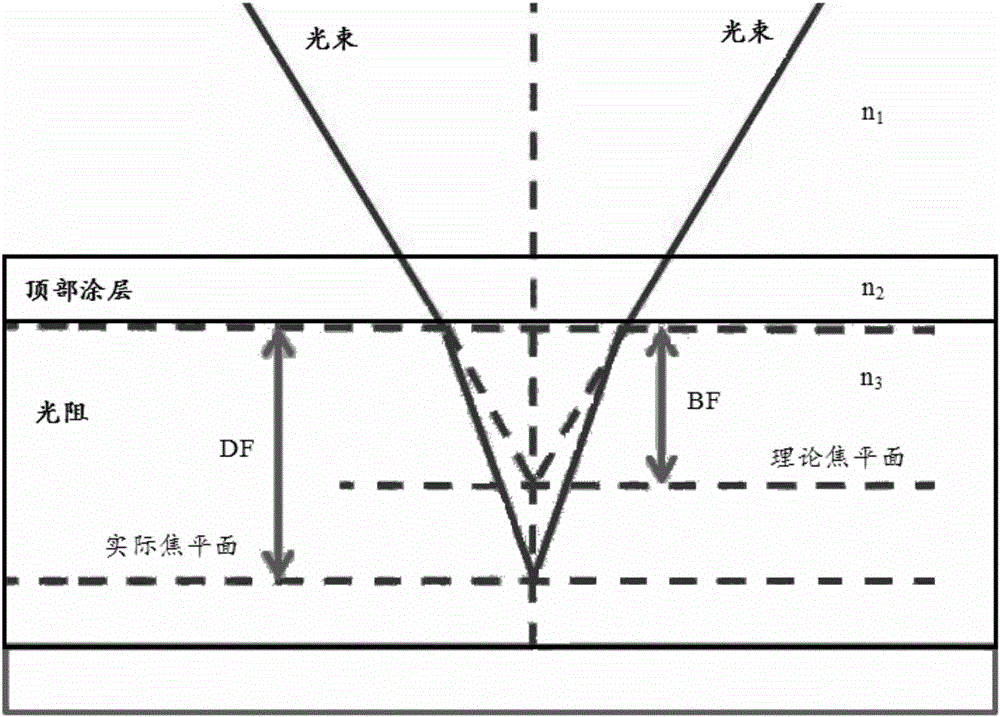
A focal plane and model technology, applied in the field of microelectronics, can solve problems such as low model accuracy requirements, affecting model extension, affecting OPC model efficiency and accuracy, etc.

Active Publication Date: 2016-06-15
SHANGHAI HUALI MICROELECTRONICS CORP
View PDF5 Cites 5 Cited by
  • Summary
  • Abstract
  • Description
  • Claims
  • Application Information

AI Technical Summary

Problems solved by technology

[0005] 2. In the obtained models, there are often many models that meet the accuracy requirements, but because they are obtained purely by error comparison, the models have strong mathematical meaning, while ignoring the physical meaning of the model, which in turn affects the extension of the model. Even overfitting occurs
[0006] In the case of a large technology node, the above two problems are not obvious due to the low accuracy requirements of the model and the small amount of calculation, but as the technology node gradually decreases, the above two problems begin to seriously affect the establishment of the OPC model efficiency and precision

Method used


Image

  • Method for determining focal plane of OPC (Optical Proximity Correction) model
  • Method for determining focal plane of OPC (Optical Proximity Correction) model
  • Method for determining focal plane of OPC (Optical Proximity Correction) model

Examples


Embodiment Construction

[0032] In order to make the content of the present invention clearer and easier to understand, the content of the present invention will be described in detail below in conjunction with specific embodiments and accompanying drawings.

[0033] In view of the problems existing in the existing technology, that is, in the process of establishing the OPC model, different focal plane settings will lead to different accuracy of the model. The current general global search method requires a lot of computing time when determining the focal plane, and there is no guarantee Extensibility of the model. The invention proposes a method for accurately determining the focal plane when building an OPC model, which can effectively improve the accuracy of the model while improving the efficiency of building the OPC model. This will play a vital role in establishing OPC models at different layers on different technology nodes in the future.

[0034] The principles and preferred embodiments of th...


PUM


Abstract

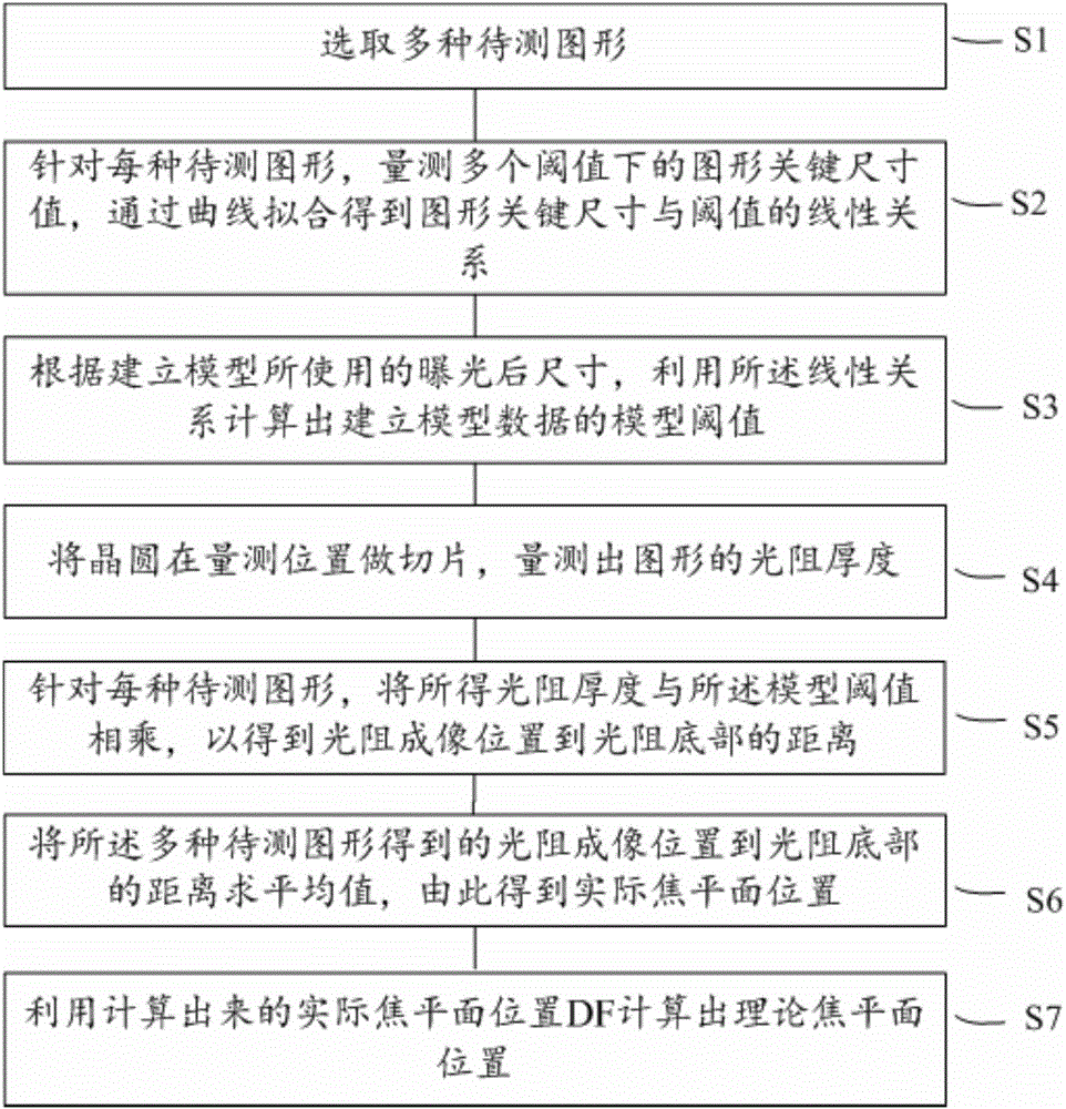
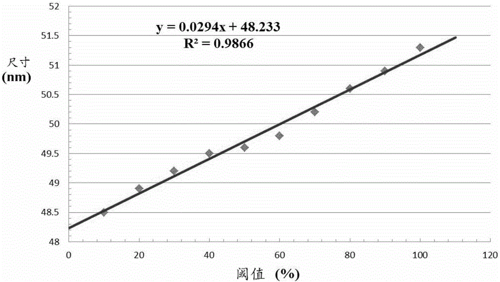
The invention provides a method for determining a focal plane of an OPC (Optical Proximity Correction) model. The method comprises the following steps: selecting a plurality of types of images to be detected; aiming at each type of image to be detected, measuring image key size values under a plurality of threshold values, and carrying out curve fitting to obtain a linear relation of the image key size values and the threshold values; calculating a model threshold value for establishing model data by using the linear relation according to a size after exposure used for establishing a model; slicing a wafer at a measuring position, and measuring the light resistance thickness of each image; aiming at each type of image to be detected, multiplying the obtained light resistance thickness by the model threshold value to obtain a distance from a light resistor imaging position to the bottom of a light resistor; and calculating an average value of the distances from the light resistor imaging position to the bottom of the light resistor, calculated by the plurality of types of images to be detected, so as to obtain an actual focal plane position; and calculating a theoretical focal plane position by using the calculated actual focal plane position.

Description

technical field [0001] The invention relates to the field of microelectronics, and more specifically, the invention relates to a method for determining the focal plane of an OPC (Optical Proximity Correction, optical proximity correction) model. Background technique [0002] The focus plane refers to the focus position of the beam on the wafer surface, including two parameters of the theoretical focus plane and the actual focus plane, which determine the imaging position during the establishment of the OPC model, and are an important optical parameter when establishing the OPC model. [0003] At present, the commonly used method to determine the focal plane is the global search method, that is, the actual focal plane and the theoretical focal plane are divided into multiple combinations with a certain step value, and then the OPC models are established respectively. By comparing the mean square errors of various models obtained, get the best model. There are two problems wi...

Claims


Application Information

Patent Timeline
Patent Type & Authority Applications(China)
IPC IPC(8): G03F1/36
CPCG03F1/36
Inventor 谭轶群于世瑞陈权
Owner SHANGHAI HUALI MICROELECTRONICS CORP
Learn More