Tracing method for determining local interference region boundary of free-form surface machining

A technology of local interference and surface processing, applied in the field of tracking, can solve the problems of local interference, low precision, improper selection of processing tool size, etc., to reduce the total length, simplify the operation, and improve the efficiency of surface processing.

Active Publication Date: 2016-06-15
YANCHENG INST OF TECH
View PDF6 Cites 12 Cited by
  • Summary
  • Abstract
  • Description
  • Claims
  • Application Information

AI Technical Summary

Problems solved by technology

[0002] In the prior art, five-axis linkage machining can greatly improve the machining accuracy and efficiency of free-form surfaces. However, due to the continuous change of the curvature of the surface and the improper selection of the machining tool size, local interference is easily generated. Tool path trajectory planning and machining tool size selection are extremely important
[0003] At present, there is a major problem in the research field of tool path planning technology for free-form surface machining: it is necessary to manually specify the size of the machining tool in advance, and most of them choose based on the experience of programmers. In order to avoid local interference, most of them use conservative tool sizes
[0009] The method of determining the boundary of the local interference area in the pre-processing method includes the discrete method, which needs to calculate the principal curvature of each discrete point on the surface, and then compare it with the tool size. In order to improve the calculation accuracy of the interference area boundary, it is necessary to reduce the discrete distance and increase the discrete Therefore, the amount of calculation is large and the accuracy is not high, and it is difficult to meet the requirements of non-interference tool path trajectory planning for complex free-form surface processing. It is necessary to further develop a new method for determining the boundary of local interference areas.

Method used


Image

  • Tracing method for determining local interference region boundary of free-form surface machining
  • Tracing method for determining local interference region boundary of free-form surface machining
  • Tracing method for determining local interference region boundary of free-form surface machining

Examples


Embodiment

[0044] Example: refer to Figure 5 As shown in , a tracking method for determining the boundaries of local interference areas in free-form surface processing, specifically includes the following steps:

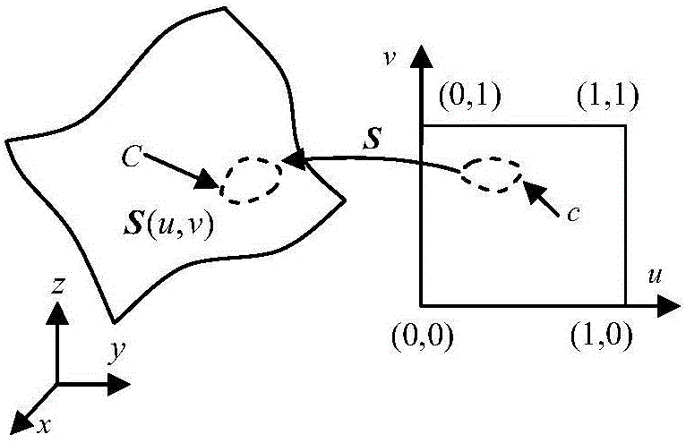
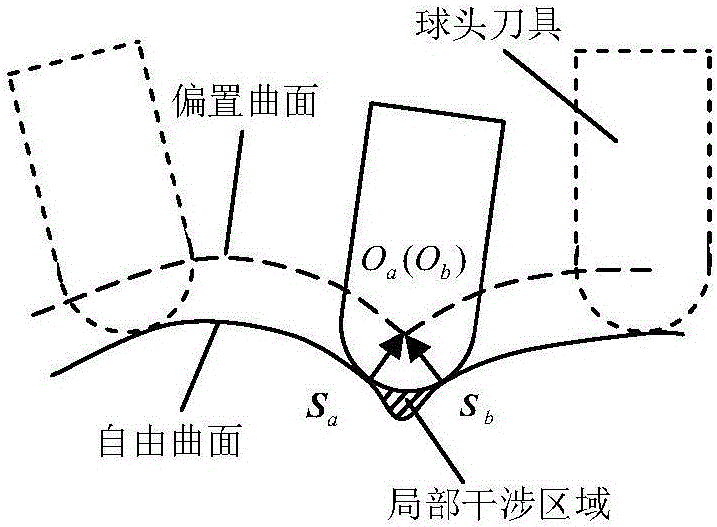
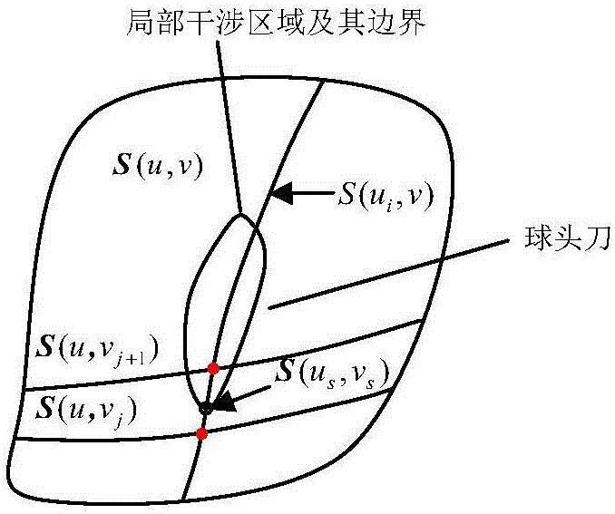
[0045] 1) Establish a free-form surface S based on point fitting of measured values ​​(such as figure 1 shown) and the offset surface S offset , the point in the parameter plane (u 0 ,v 0 ) corresponding to the point S(u on the free-form surface S 0 ,v 0 ) and the offset surface S offset point S on offset (u 0 ,v 0 ) between the corresponding principal curvature relation is: Set the boundary tracking condition of the local interference area: k max (u,v)=k tool ; where: k m is the principal curvature on the free-form surface S; k m_offset is the offset surface S offset on the principal curvature, d is the offset surface S offset Distance to free-form surface S, k max (u, v) is the maximum principal curvature of the point on the free surface S, k tool is the ma...


PUM


Abstract

The invention discloses a tracing method for determining a local interference region boundary of free-form surface machining. Through analysis of principal curvatures of a free-form surface and an isometric offset surface, the local interference region boundary condition of the free-form surface machining is obtained. A tracing initial point of the local interference region boundary is obtained through combination of a surface discrete method and a dichotomy method. A rough point of the local interference region boundary is obtained through tracking along an osculating circle of the interference region boundary from the initial point. A precision point of the local interference region boundary is calculated through iteration by using a gradient method. Two tracing judgmental end conditions are obtained according to the condition that whether the local interference region boundary is enclosed on the surface. The tracing method for determining local interference region boundary of the free-form surface machining has the advantages that the tracing method is suitable for fast tracing and determining the interference region boundary of the complex free-form surface machining, a tool path track is regionally planned, a total length of the tool path track is reduced, and the surface machining efficiency is improved.

Description

technical field [0001] The invention relates to a tracking method, in particular to a tracking method for determining the boundary of a local interference area in free-form surface processing. Background technique [0002] In the prior art, five-axis linkage machining can greatly improve the machining accuracy and efficiency of free-form surfaces. However, due to the continuous change of the curvature of the surface and the improper selection of the machining tool size, local interference is easily generated. Tool path trajectory planning and machining tool size selection are extremely important. [0003] At present, there is a major problem in the research field of tool path trajectory planning technology for free-form surface machining: it is necessary to manually specify the size of the machining tool in advance, and most of them choose based on the experience of programmers. In order to avoid local interference, most of them use conservative tool sizes. Therefore, the t...

Claims


Application Information

Patent Timeline
Patent Type & Authority Applications(China)
IPC IPC(8): G05B19/19
CPCG05B19/19G05B2219/35158
Inventor 赵世田付莹莹曾勇郑雷周博
Owner YANCHENG INST OF TECH
Why Eureka
Try Eureka