Connector
A technology of connectors and contact parts, which is applied in the directions of connections, instruments, and parts of connecting devices, etc., can solve the problems of damage, the reduction of the elastic restoring force of the contact terminal 920, and the damage of the contact terminal 920, so as to achieve the effect of preventing damage.
- Summary
- Abstract
- Description
- Claims
- Application Information
AI Technical Summary
Problems solved by technology
Method used
Image

Examples
no. 1 example
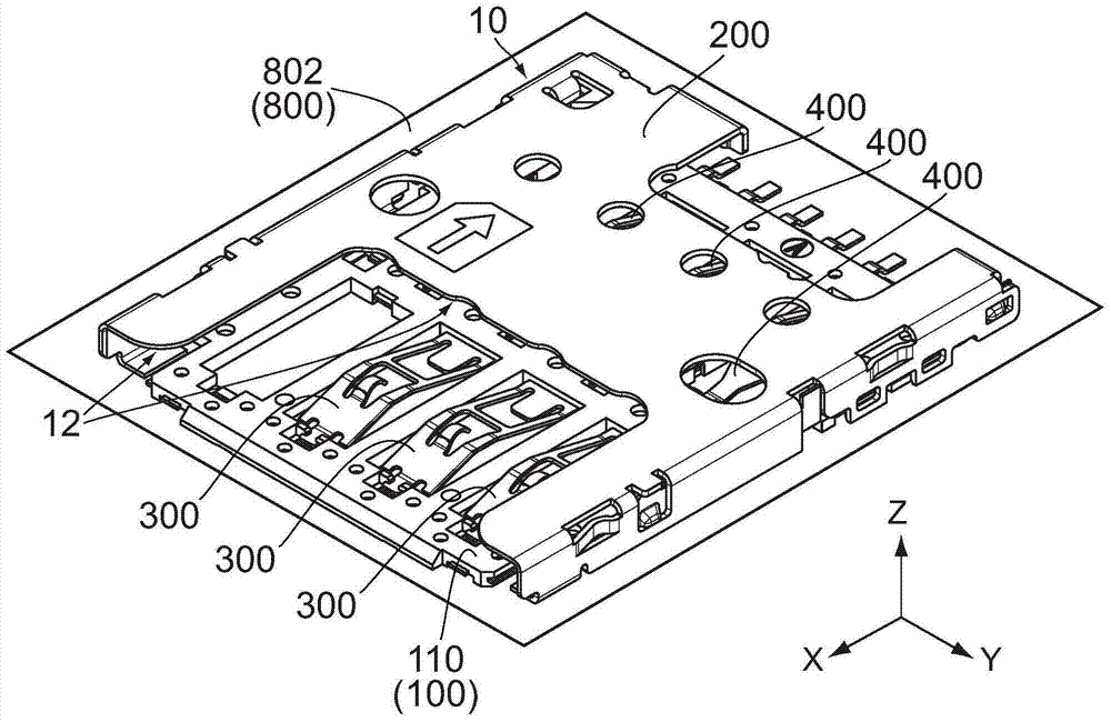
[0038] refer to figure 1 , 10 , is the connector 10 of the first embodiment of the present invention, and the card 600 can be connected to the connector 10 by moving the card 600 backward or in the negative direction of the X axis along the front-rear direction (X-axis direction). In this embodiment, the card 600 can be inserted into the connector 10 along the negative direction of the X-axis (insertion direction) and can be moved out of the connector 10 along the positive direction of the X-axis (removal direction). refer to figure 1 , 8 , 9. In use, the connector 10 is mounted on the mounting surface 802 of the circuit board 800, however, the present invention is not limited thereto, for example, the connector 10 may be a plug-in connector.
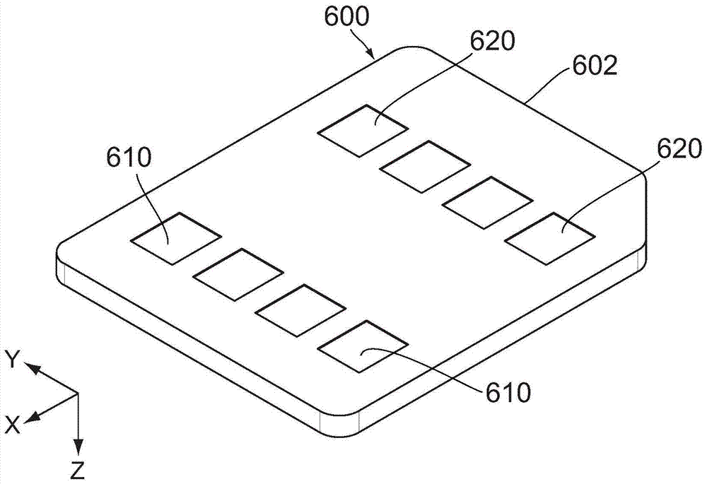
[0039] refer to figure 2 , the card 600 is a small SIM card, which has four electrodes 610 and four electrodes 620, and the electrodes 610 and 620 are arranged on the upper surface of the card 600, or the negative surface of the ...
no. 2 example
[0076] refer to Figure 13 , the connector 10A of the second embodiment of the present invention may be different from the card 600 (see figure 2 ) card (not shown). In use, similar to the connector 10 , the connector 10A of this embodiment is installed on the mounting surface 802 of the circuit board 800 , and the differences between the connector 10A and the connector 10 will be described in detail below.
[0077] refer to Figure 13 to Figure 15 , The connector 10A of the present embodiment includes a holding member 100A mainly made of an insulating material, a housing 200A made of metal, a plurality of front side contact portions (contact portions) 300A made of metal, and A plurality of rear contact portions 400A. In the up-down direction (Z-axis direction), the housing 200A is connected to the holding member 100A from above and together with the holding member 100A forms an accommodating portion 12A that at least partially houses a card (not shown) connected to the co...
no. 3 example
[0091] refer to Figure 18 , the connector 10B of the third embodiment of the present invention can be used with similar cards 600 (such as figure 2 ) card (not shown). Similar to the connector 10 , the connector 10B of this embodiment is also mounted on the mounting surface 802 of the circuit board 800 . The structure of the connector 10B will be described in detail later, especially the difference between the connector 10B and the connector 10 .
[0092] refer to Figure 18 to Figure 20 , The connector 10B of this embodiment includes a holding member 100B mainly made of insulating material, a housing 200B made of metal, three front side contact parts (contact parts) 300B made of metal, and a metal body made of metal. Three rear-side contact portions 400B, along the up-down direction (Z-axis direction), the housing 200B is connected to the holding member 100B from above and together with the holding member 100B forms an accommodating portion 12B that at least partially acc...
PUM
 Abstract
Description
Claims
Application Information
 - Generate Ideas
- Intellectual Property
- Life Sciences
- Materials
- Tech Scout
- Unparalleled Data Quality
- Higher Quality Content
- 60% Fewer Hallucinations
Browse by: Latest US Patents, China's latest patents, Technical Efficacy Thesaurus, Application Domain, Technology Topic, Popular Technical Reports.
© 2025 PatSnap. All rights reserved.Legal|Privacy policy|Modern Slavery Act Transparency Statement|Sitemap|About US| Contact US: help@patsnap.com