Lens driving apparatus

a technology of driving apparatus and lens, which is applied in the direction of printers, instruments, cameras, etc., can solve the problems of degrading the performance increasing the time and cost of manufacturing, and complicated manufacturing process of the lens driving apparatus, so as to reduce the entire lens driving apparatus, simplify the configuration, and prevent the manufacturing process from becoming complicated

Active Publication Date: 2011-02-01
SANKYO SEIKI MFG CO LTD
View PDF10 Cites 20 Cited by
  • Summary
  • Abstract
  • Description
  • Claims
  • Application Information

AI Technical Summary

Benefits of technology

[0018]According to at least an embodiment the present invention, it may comprise a movable body, a support body for supporting the movable body to move in the lens optical axis direction, and a drive mechanism for driving the support body, wherein the movable body is provided with an extension portion that is extended toward the outer periphery, and a moving path and a movement-stopping portion are formed to at least a member of the drive mechanism mounted on the support member or to the support body, the moving path allowing the extension portion to move in the optical axis direction when the movable body is moved in the optical axis direction and the movement-stopping portion regulating the moving range of the movable body. Therefore, the extension portion provided at the outer circumference of the movable body can move only within the range until it comes into contact with the movement-stopping portion. For this reason, even when the apparatus receives a strong shock caused by the impact of being dropped, at least one of the following problems can be prevented: the problem caused by excessive displacement of the movable body in the optical axis direction, the problem caused by the displacement of the movable body in the left-right direction perpendicular to the optical axis, or the problem caused by the rotational displacement of the movable lens in the circumferential direction. With the above-mentioned effects of the extension portion and the movement-stopping portion, the movable body is kept from excessive displacement beyond a predetermined range (for example, rotation at more than a predetermined angle). Also, unlike a conventional lens driving apparatus, a guide mechanism in a complicated shape is not necessary but the extension portion is simply formed to the movable body to add a rotating-prevention function, resulting in reduced time and cost of manufacturing and increased utility. Further, the position at which the extension portion makes contact with the movement-stopping portion is in the vicinity of the outer circumference of the lens moving body, not in the vicinity of the lens (sensor surface). In this way, wear powder, which may be produced when the extension portion makes contact with the movement-stopping portion, is prevented from adhering to the sensor surface.
[0037]Also, in the lens driving apparatus of at least an embodiment of the present invention, the arm portions of the spring member are arranged in relatively wider corner portions even when the space bounded by the inner periphery of the frame portion and the outer circumference of the movable body is narrow; therefore, the number of the elongated [parallel] portions and the turning portions can be increased. For this reason, even when the movable body is excessively displaced in the optical axis direction, displaced in the left-right direction perpendicular to the optical axis, rotationally displaced in the circumferential direction or displaced in the diagonal direction (tilt direction) with respect to the optical axis because of impact, etc., the spring members demonstrate excellent vibration resistance and shock resistance. Also, even when the movable body is excessively displaced in the optical axis direction, displaced in the left-right direction perpendicular to the optical axis, rotationally displaced in the circumferential direction or displaced in the diagonal direction (tilt direction) with respect to the optical axis because of impact, etc., the spring members are provided with sufficient rigidity to endure the stress caused by such displacements; therefore, plastic deformation of the arm portions can be avoided for sure.

Problems solved by technology

Therefore, the manufacturing process of the lens driving apparatus becomes complicated, increasing time and cost of manufacturing.
If wear powder adheres to the sensor surface, the photographed images become blurred, thus degrading the performance of the lens driving apparatus.
However, when the spring member disclosed in Patent Reference 1, 2 is used in the lens driving apparatus having such a configuration, there is not much freedom in designing the arm portion and only an insufficient spring property can be demonstrated.
Also, when the movable body in the lens driving apparatus receives a strong shock from being dropped and moves abruptly in the direction perpendicular to the optical axis direction (the left-right direction or circumferential direction) or the diagonal direction (the tilt direction) with respect to the optical axis direction, a conventional spring member may easily suffer from plastic deformation or breaking, causing problems such as poor stroke in the lens driving apparatus.

Method used


Image

  • Lens driving apparatus
  • Lens driving apparatus
  • Lens driving apparatus

Examples


embodiment 1

Overall Configuration

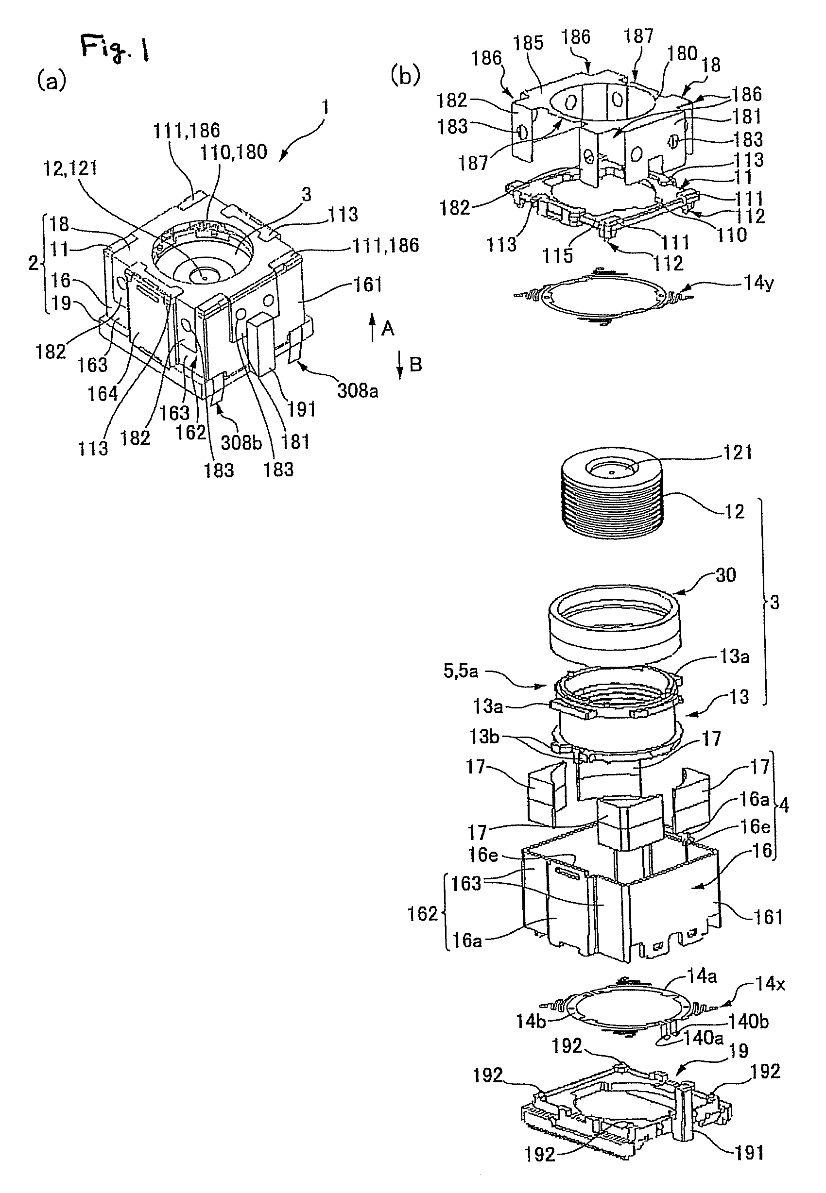
[0048]FIG. 1 (a) and (b) are respectively an external appearance view of the lens driving apparatus of Embodiment 1 of the present invention, observing the front of the apparatus diagonally from the top, and a perspective disassembly view.

[0049]Used in thin cameras such as digital cameras or camera phones, the lens driving apparatus 1 of this embodiment shown in FIG. 1 and FIG. 2 (a) moves three lenses 121 in both the A direction (to the front) and the B direction (to the back) along the optical axis, the A direction in which the lenses are moved toward a photographic subject (toward an object) and the B direction in which the lenses are moved in the opposite direction from the photographic subject (toward an image). It is in a rectangular parallelepiped. The lens driving apparatus 1 has a movable body 3 holding a cylindrical lens barrel 12 equipped with the three lenses 121 and a fixed aperture inside thereof, a drive mechanism 5 that moves the movable body 3 a...

modification example of embodiment 1

[0098]FIG. 6 is a horizontal cross-sectional view of a lens driving apparatus of Modification Example of Embodiment 1. In the lens driving apparatus 1 shown in FIG. 2, the magnetic circuit is constituted by the back yoke 16, the magnets 17, and the coil 30; however, an inner yoke 21 may be added to form the magnetic circuit as in a lens driving apparatus 1A shown in FIG. 6 (a). In this way, a magnetic flux can be induced in a desired direction (leakage of magnetic flux can be reduced), providing the stable electromagnetic force.

[0099]As in a lens driving apparatus 1B shown in FIG. 6 (b), the shape of the coil 30 may be changed to use it as a stopper. In other words, the coil 30 moves together with the sleeve 13 in the moving-coil-type lens driving apparatus 1B; for example, when the sleeve 13 is displaced upwardly in the figure by some kind of shock, the coil 30 is also displaced and a modified portion 30a of the coil 30 (an example of the extension portion) makes contact with the m...

embodiment 2

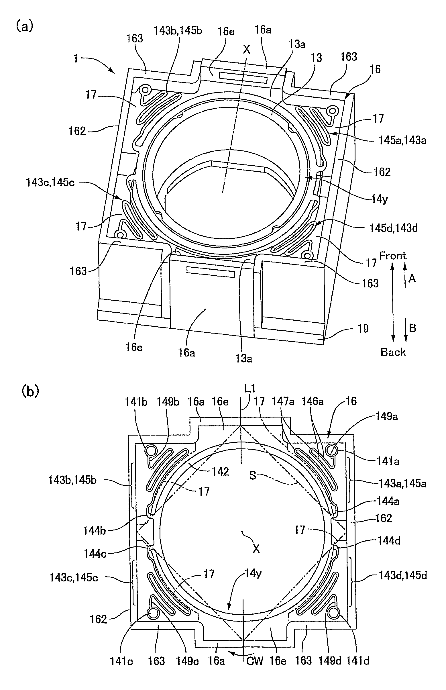
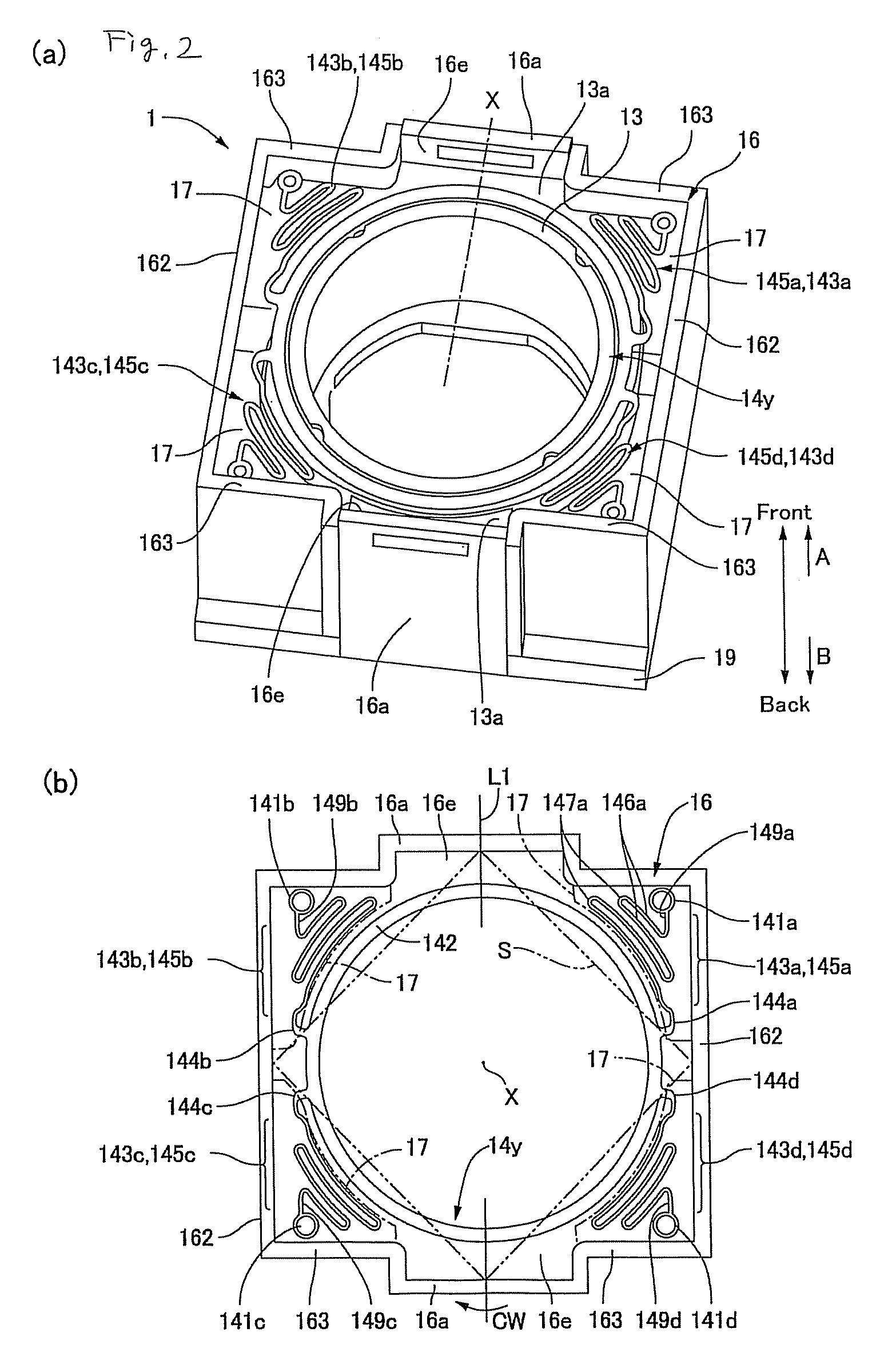
[0102]FIG. 7 is a plan view of a lens driving apparatus of Embodiment 2 of the present invention, with the cover off. Since the basic configuration of this embodiment remains the same as Embodiment 1, the overall configuration is described referring to FIG. 1 (a) and (b), and the same codes are given to the common members and their description is omitted.

[0103]As shown in FIG. 1 (a) and (b), even in the lens driving apparatus 1 of this embodiment, the spring members 14x and 14y are respectively arranged between the back yoke 16 and the holder 19 and between the back yoke 16 and the case 11. The spring members 14x and 14y share the same basic configuration; therefore, the spring member 14y arranged between the back yoke 16 and the case 11 is used to describe the configuration.

[0104]As shown in FIG. 7, the spring member 14y is provided, in the same manner as Embodiment 1, with four small annular outside joint portions 141a, 141b, 141c and 141d held between the back yoke 16 and the cas...


PUM


Abstract

A lens driving apparatus may include a movable body holding lenses; a support body for supporting said movable body to move in the optical axis direction of said lenses; and a drive mechanism for driving said movable body in the optical axis direction; wherein said movable body is provided with an extension portion that is extended toward the outer periphery, and a moving path and a movement-stopping portion are formed to at least a member of said drive mechanism mounted on the support body or to said support body, said moving path allowing said extension portion to move in the optical axis direction when said movable body is moved in the optical axis direction and said movement-stopping portion regulating the moving range of said movable body as said extension portion makes contact with said movement-stopping portion.

Description

[0001]This application claims priority under 35 U.S.C. 119, to Japanese applications, JP 2006-272551 filed on Oct. 4, 2006 and JP 2007-050357 filed on Feb. 28, 2007.TECHNICAL FIELD[0002]The disclosure relates to a lens driving apparatus that drives a lens to be displaced in the optical axis direction in order to focus an image of a subject to be photographed.BACKGROUND[0003]The widespread availability of camera phones having a camera function in recent years has increased the opportunities for users to photograph various kinds of photographic subjects. For example, a photographic subject at a distance from the camera lens, such as a friend or scenery, is photographed (normal snapshot) or a photographic subject at a close distance from the camera lens, such as a bus time schedule or flower petals, is photographed (close-up photography).[0004]For close-up photography (macro photography), the camera lens needs to be positioned slightly closer to the photographic subject than for a norm...

Claims


Application Information

Patent Timeline
Patent Type & Authority Patents(United States)
IPC IPC(8): G02B7/02
CPCG02B7/04G03B3/10
Inventor OTSUKI, NOBORUWADA, AKIHITOSATO, TSUNEO
Owner SANKYO SEIKI MFG CO LTD
Why Eureka
Try Eureka