System and method for controlling output power of electric heater

An electric heater and output power technology, applied in ohmic resistance heating, ohmic resistance heating circuit diagram, electric heating device, etc., can solve the problems of indoor temperature fluctuation, air outlet temperature and heating capacity drop, low output power of electric heater, etc. Achieve the effect of satisfying stability and comfort

An electric heater and output power technology, applied in ohmic resistance heating, ohmic resistance heating circuit diagram, electric heating device, etc., can solve the problems of indoor temperature fluctuation, air outlet temperature and heating capacity drop, low output power of electric heater, etc. Achieve the effect of satisfying stability and comfort

CN105682261AInactive Publication Date: 2016-06-15SICHUAN CHANGHONG ELECTRIC CO LTD

Image

  • System and method for controlling output power of electric heater
  • System and method for controlling output power of electric heater
  • System and method for controlling output power of electric heater

Examples


Embodiment 1

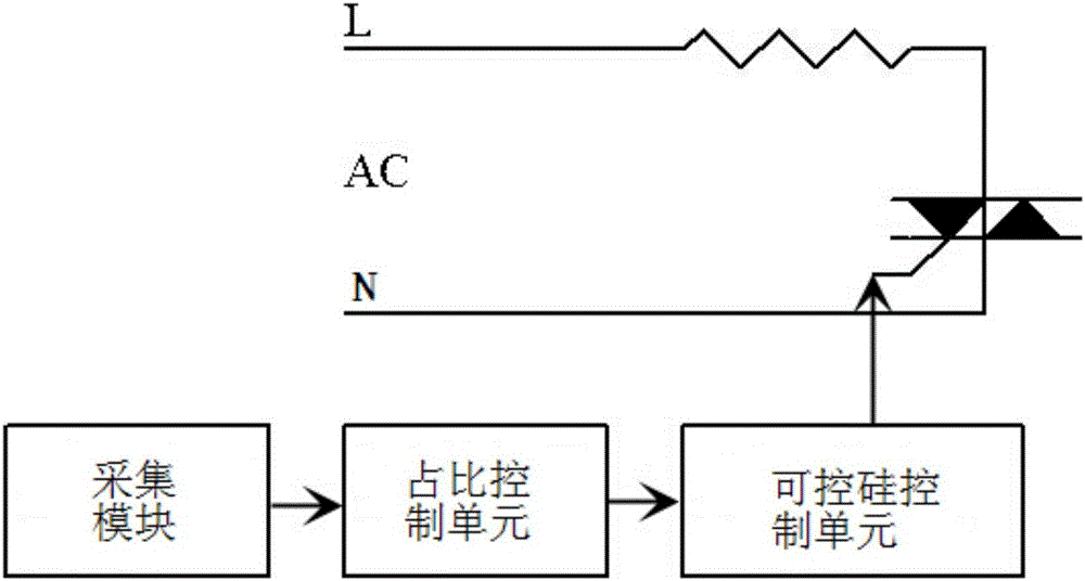
[0037] Such as figure 1 The system for controlling the output power of an electric heater is shown, the electric heater is powered by an AC power supply, and it is mainly composed of an acquisition unit, a duty cycle control unit and a thyristor control unit that are electrically connected in sequence;

[0038] The collection unit is electrically connected to the AC power supply, and is used to collect the AC power supply cycle, the AC power supply voltage and the indoor temperature;

[0039] The duty cycle control unit is used to receive and collect the cycle of the AC power supply, the voltage of the AC power supply, and the indoor temperature, and obtain the first duty cycle value according to the cycle of the AC power supply, the voltage of the AC power supply, and the indoor temperature, and then obtain the first duty cycle value according to the first duty cycle value, the AC power The duty cycle value of the thyristor control signal is obtained from the power supply vol...

Embodiment 2

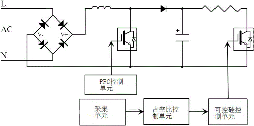
[0048] Such as figure 2 The shown system for controlling the output power of an electric heater is mainly composed of an acquisition unit, a PFC control unit, a duty cycle control unit and a thyristor control unit that are electrically connected in sequence;

[0049] The collection unit is electrically connected to the AC power supply, and is used to collect the AC power supply cycle, the AC power supply voltage and the indoor temperature;

[0050] The PFC control unit is used to output a DC voltage according to the AC power supply voltage and the rated power of the electric heater;

[0051] The duty cycle control unit is used to receive and collect AC power cycle, DC voltage and indoor temperature, and obtain the first duty cycle value according to the AC power cycle, DC voltage and indoor temperature, and then obtain the first duty cycle value according to the first duty cycle value, DC voltage and indoor temperature. The indoor temperature obtains the duty cycle value of ...


PUM


Abstract

The invention discloses a system and a method for controlling an output power of an electric heater. The system mainly comprises a collection unit, a duty ratio control unit and a thyristor control unit, which are electrically connected with one another in sequence. The method comprises the steps as follows: the collection unit collects an AC power cycle, an AC power voltage and an indoor temperature; the duty ratio control unit receives collected AC power cycle, AC power voltage and indoor temperature, obtains a first duty ratio value according to the AC power cycle, the AC power voltage and the indoor temperature, and obtains the duty ratio value of a thyristor control signal according to the first duty ratio value, the AC power voltage and the indoor temperature; and the thyristor control unit is used for receiving the duty ratio value of the thyristor control signal, and controlling opening and closing of a thyristor according to the duty ratio value of the thyristor control signal, so that the output power of the electric heater is controlled. The requirements of a user on indoor temperature stability and comfort are met by properly adjusting and reducing the output power of the electric heater.

Description

technical field [0001] The invention relates to the technical field of energy saving and environmental protection, in particular to a system and method for controlling the output power of an electric heater. Background technique [0002] At present, in electrical products such as heating and cooling air conditioners and electric heaters, there are different forms of electric heating as the main or auxiliary heating appliances. Heating can be achieved by heat pump air conditioners, electric heaters directly, or both. Among them, electric heating is generally based on whether it is turned on or not. Taking the work of an air-conditioning heat pump as an example, for example, a 1000W electric heater has two states of on or off, and the electric heater is protected by a mechanical thermostat and a fuse. The air outlet structure of the indoor unit of the air conditioner is usually made of plastic parts. Since the heat pump of the air conditioner itself has a large heating capacit...

Claims


Application Information

Patent Timeline
15 Jun 2016
Publication
CN105682261A
IPC
H05B1/02; H05B3/00
CPC
H05B1/0275; H05B3/0019
Inventors
阳丹; ι«˜ε‘ε†›