Vehicle seat air-conditioner

An air-conditioning device and seat technology, applied to vehicle seats, special positions of vehicles, vehicle components, etc., can solve the problems of small air volume, longer time, and less heat, and achieve the effect of maintaining comfort

Inactive Publication Date: 2016-06-15
DENSO CORP
View PDF8 Cites 7 Cited by
  • Summary
  • Abstract
  • Description
  • Claims
  • Application Information

AI Technical Summary

Problems solved by technology

[0009] However, in the vehicle seat air conditioner disclosed in Patent Document 1, since the air volume of the air passing through the ventilation passage is small during the period when the temperature adjustment of the blown air is insufficient, the amount of heat per unit time moving from the air to the ventilation passage is smaller
Therefore, the temperature of the ventilation passage is not likely to approach the temperature of the air passing through the ventilation passage, and the time required for the air to be blown out to the occupants to reach a sufficiently regulated temperature may become longer.

Method used


Image

  • Vehicle seat air-conditioner
  • Vehicle seat air-conditioner
  • Vehicle seat air-conditioner

Examples


no. 1 approach

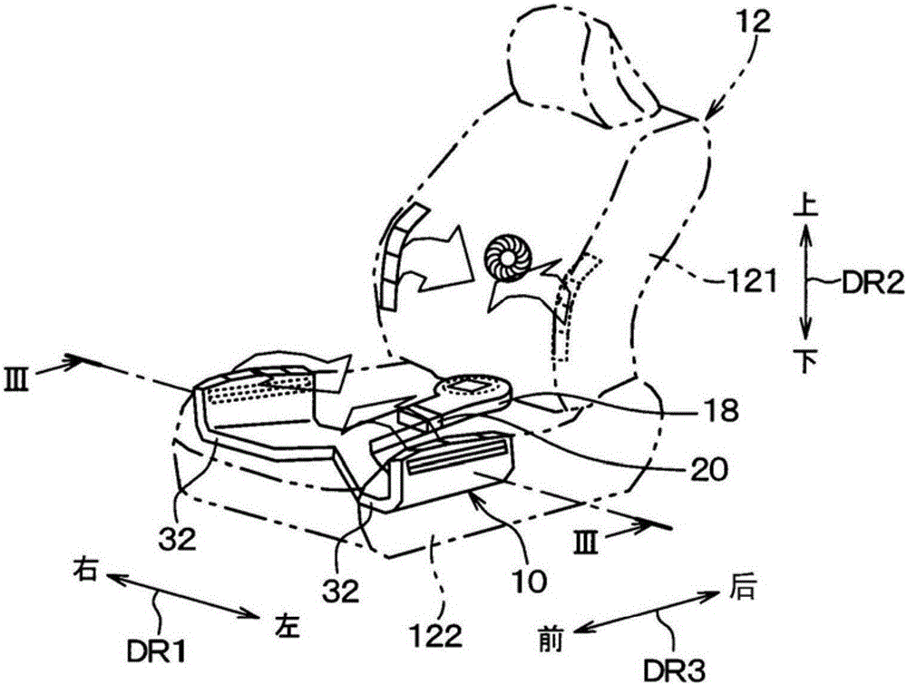
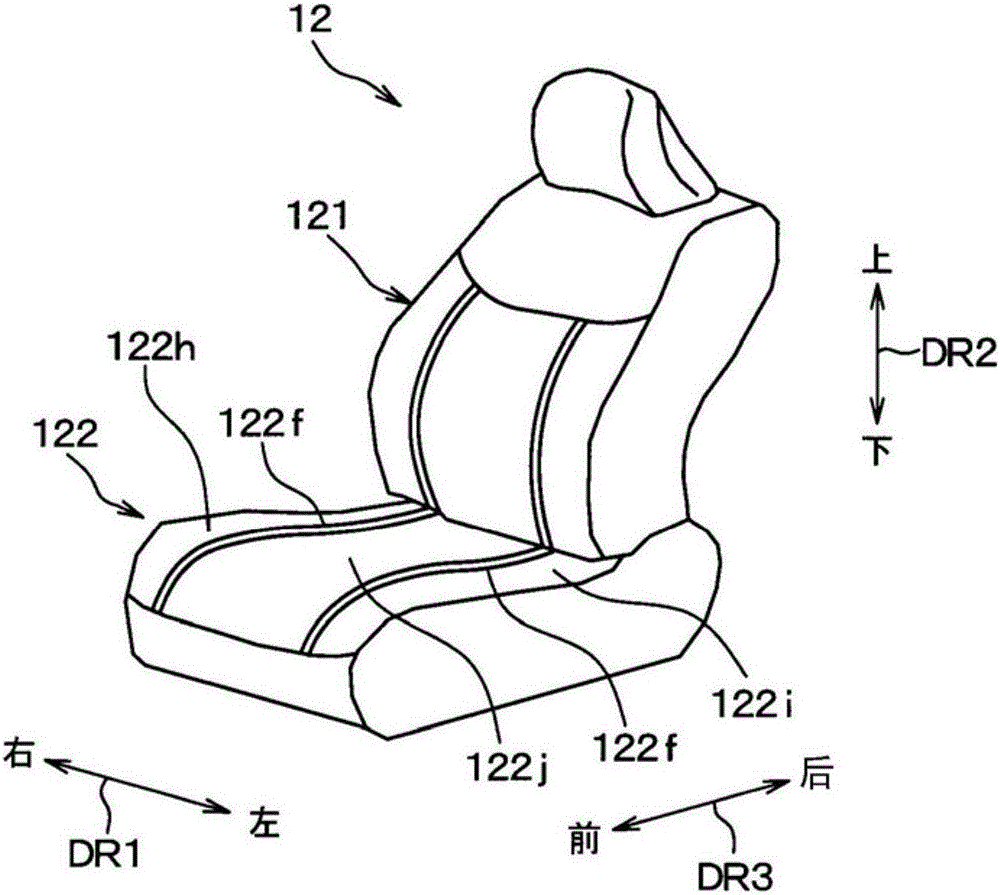
[0039] figure 1 It is a schematic perspective view showing a vehicle seat air conditioner 10 according to the present embodiment and a vehicle seat 12 to which the vehicle seat air conditioner 10 is mounted. The seat back 121 and the seat cushion 122 of the vehicle seat 12 are respectively equipped with a vehicle seat air conditioner, but the vehicle seat air conditioner 10 (hereinafter simply referred to as the seat air conditioner 10 ) to which the present invention is applied is A vehicle seat air conditioner mounted on the seat cushion 122 . In addition, in figure 1 Arrow DR1 indicates the left-right direction DR1 of the vehicle, that is, the vehicle width direction DR1, arrow DR2 indicates the vehicle's up-down direction DR2, that is, the vehicle up-down direction DR2, and arrow DR3 indicates the vehicle's front-rear direction DR3, that is, the vehicle front-rear direction DR3.

[0040] figure 1 The illustrated vehicle seat 12 includes: a seat back 121 serving as a bac...

no. 2 approach

[0070] Next, a second embodiment of the present invention will be described. In this embodiment, the content different from the above-mentioned first embodiment will be mainly described. In addition, descriptions of the same or equivalent parts as those in the above-mentioned embodiment are omitted or simplified. The same applies to the third and subsequent embodiments described later.

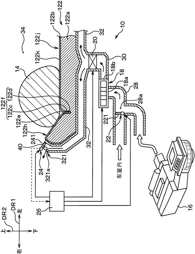
[0071] Figure 6 It is a sectional view of the seat cushion 122 and the seat air conditioner 10 of the present embodiment, and corresponds to the first embodiment. image 3 diagram. Figure 7 It is a sectional view of the seat cushion 122 and the seat air conditioner 10 of the present embodiment, and corresponds to the first embodiment. Figure 4 diagram. Figure 7 compared to Figure 6 In other words, the direction of the air guide member 242 of the blown air switching device 24 is different.

[0072] Such as Figure 6 and Figure 7 As shown, the ventilation pipe 32 for blowing out i...

no. 3 approach

[0078] Next, a third embodiment of the present invention will be described. In this embodiment, the content different from the above-mentioned first embodiment will be mainly described.

[0079] Figure 8 It is a sectional view of the seat cushion 122 and the seat air conditioner 10 of the present embodiment, and corresponds to the first embodiment. image 3 diagram. Figure 9 It is a sectional view of the seat cushion 122 and the seat air conditioner 10 of the present embodiment, and corresponds to the first embodiment. Figure 4 diagram. exist Figure 8 Among them, the rotational position of the opening and closing door 243 of the blowing wind switching device 24 is related to Figure 9 different.

[0080] Such as Figure 8 and Figure 9 As shown, the ventilation pipe 32 for blowing out in this embodiment does not go around the side of the seat cushion 122, and the ventilation pipe 32 for blowing out does not have the air blowing portion 321 (refer to image 3 ). A...


PUM


Abstract

A control unit causes a blowout air switching device (24) to switch an air blowout portion (321) to a first blowout state if air blown from the air blowout portion (321) is in a pre-conditioned state. If air blown from the air blowout portion (321) is in a conditioned state, the control unit causes the blowout air switching device (24) to switch the air blowout portion (321) to a second blowout state. Furthermore, in the first blowout state, a first air outlet (321a) is opened while a second air outlet (321b) is closed. Conversely, in the second blowout state, the first air outlet (321a) is closed while the second air outlet (321b) is opened. Thus, it is possible to avoid blowing of insufficiently conditioned air against a seated person, without having to limit the volume of blowout air at the start of air-conditioning by a seat air-conditioner (10).

Description

[0001] Cross-reference of related applications [0002] This application is based on the JP Patent application 2013-222118 for which it applied on October 25, 2013, The indication of this application is referred and is used here. technical field [0003] The present invention relates to a vehicle seat air conditioner that blows air-conditioning air to a vehicle seat. Background technique [0004] As a conventional technology related to a vehicle seat air conditioner, for example, Patent Document 1 discloses a vehicle seat air conditioner in which air-conditioning air is blown from a plurality of fine holes formed in a seat surface. In the vehicle seat air conditioner of Patent Document 1, when the seat air conditioner is started when the vehicle interior is cooled or heated, the blown air velocity from the seat surface is limited so that the blown air velocity is 0.4 m / s or less. wind speed. [0005] prior art literature [0006] patent documents [0007] Patent Document...

Claims


Application Information

Patent Timeline
Patent Type & Authority Applications(China)
IPC IPC(8): B60H1/34A47C7/74B60H1/00
CPCB60H2001/003B60N2/5628B60N2/5657B60H1/00285B60H1/00564B60H1/00678B60H1/00842B60H1/00871
Inventor 田中祐介新美康彦藤井贵央
Owner DENSO CORP
Why Eureka
Try Eureka