
Thread self-locking type manual clamping fixture

A self-locking, clamping clamp technology, applied in the direction of manufacturing tools, workpiece clamping devices, etc., can solve the problems of small force ratio, complex structure and manufacturing process, etc., to achieve small size, light weight, simple and compact structure Effect

Inactive Publication Date: 2016-06-22
XIAN ZHONGZHI HUIZE PHOTOELECTRIC TECH
View PDF0 Cites 1 Cited by
  • Summary
  • Abstract
  • Description
  • Claims
  • Application Information

AI Technical Summary

Problems solved by technology

[0002] At present, clamping devices are widely used in all walks of life. Clamping devices generally adopt wedge clamping, eccentric clamping, centering clamping or hinge clamping. The above clamping methods have structures and manufacturing processes. Relatively complex, relatively small boost ratio and other issues

Method used


Image

  • Thread self-locking type manual clamping fixture

Examples


Embodiment Construction

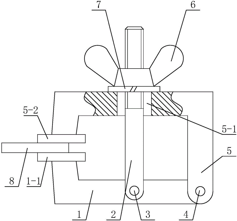
[0021] Such as figure 1 A threaded self-locking manual clamping fixture shown includes an L-shaped support plate 1 for supporting, and also includes a half-shaped pressure plate 5 that cooperates with the L-shaped support plate 1 for clamping a workpiece 8 and The screw rod 2 and the compression nut 6 that cooperate with each other to form a thread pair; the middle part of the L-shaped support plate 1 is rotationally connected with the lower end of the screw rod 2 through a pin one 3, and one end of the L-shaped support plate 1 is connected to the half-mouth One end of the glyph pressing plate 5 is rotationally connected by bearing pin two 4, and the said compression nut 6 is installed after the said screw rod 2 upper end passes through the light hole 5-1 that is arranged on the middle part of the said half-shaped glyph pressing plate 5, and said compression An anti-slip gasket 7 is arranged between the nut 6 and the half-shaped pressing plate 5, the opening end of the L-shape...


PUM


Abstract

The invention discloses a thread self-locking type manual clamping fixture which comprises an L-shaped supporting plate, a n-shaped pressing plate, a threaded rod and a compression nut. The middle portion of the L-shaped supporting plate is rotatably connected with the lower end of the threaded rod through a first hinge pin. One end of the L-shaped supporting plate is rotatably connected with one end of the n-shaped pressing plate through a second hinge pin. The upper end of the threaded rod penetrates through an unthreaded hole in the middle of the n-shaped pressing plate and then is provided with the compression nut. An anti-skid gasket is arranged between the compression nut and the n-shaped pressing plate. A first pressure foot is fixedly arranged at the open end of the L-shaped supporting plate. A second pressure foot matched with the first pressure foot is fixedly arranged at the open end of the n-shaped pressing plate. The thread self-locking type manual clamping fixture has the following characteristics of being reasonable in design, simple in structure, convenient to operate, small in size, low in weight, convenient to mount and dismount, reliable in clamping, large in force increasing ratio, good in self-locking performance, low in production cost and convenient to use and popularize.

Description

technical field [0001] The invention relates to a clamping device, in particular to a threaded self-locking manual clamping fixture. Background technique [0002] At present, clamping devices are widely used in all walks of life. Clamping devices generally adopt wedge clamping, eccentric clamping, centering clamping or hinge clamping. The above clamping methods have structures and manufacturing processes. Relatively complex, relatively small boost ratio and other issues. Contents of the invention [0003] The purpose of the present invention is to overcome the deficiencies in the above-mentioned prior art and provide a threaded self-locking manual clamping fixture, which has reasonable design, simple structure, convenient operation, small size, light weight, convenient disassembly and assembly, and reliable clamping. The booster ratio is large, the self-locking performance is good, the production cost is low, and it is easy to popularize and use. [0004] In order to ach...

Claims


Application Information

Patent Timeline
IPC IPC(8): B25B11/00
Inventor 侯鹏
Owner XIAN ZHONGZHI HUIZE PHOTOELECTRIC TECH
Learn More