
Paper clipping and shaping device

A sizing device and paper technology, applied in the field of slitting technology, can solve the problems of high manufacturing and use costs, difficulty, and inability to cut paper, and achieve low manufacturing and use costs, high cutting reliability, and high cutting efficiency. Effect

Inactive Publication Date: 2016-06-22
FOSHAN UNIVERSITY
View PDF5 Cites 0 Cited by
  • Summary
  • Abstract
  • Description
  • Claims
  • Application Information

AI Technical Summary

Problems solved by technology

[0002] The existing paper cutting technology generally adopts the knife cutting technology, which uses a cutter to cut the paper. This cutting technology is more effective for cutting the paper in sections. However, if you want to cut the paper from the Cut a piece of paper out of the middle of the paper. Since the cutting knives are all yin and yang knives, it is not easy to manufacture a knife with the same shape as the cut paper. Even if it can be manufactured, the cost of manufacturing and use is also It is very high, and once the cutter is worn out, it is not easy to restore the sharpness of the cutter by grinding. If multiple cutters are combined to form a combined cutter with the same shape as the cut paper , the gap formed between the cutters is not easy to solve, and the existence of the gap makes it impossible to completely cut the paper

Method used


Image

  • Paper clipping and shaping device
  • Paper clipping and shaping device
  • Paper clipping and shaping device

Examples


Embodiment Construction

[0012] Now in conjunction with accompanying drawing and embodiment the present invention is described in further detail:

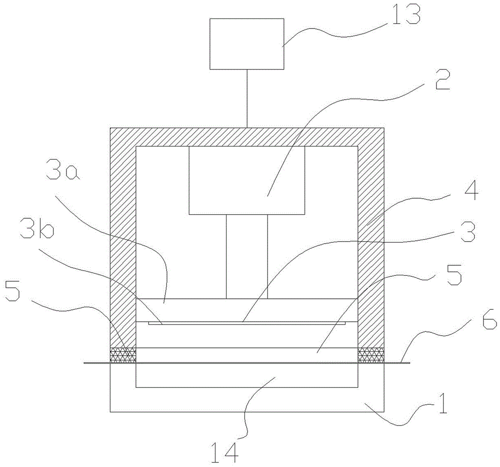
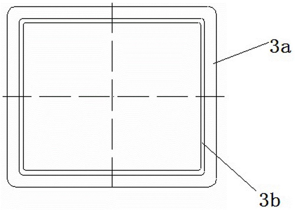
[0013] Such as figure 1 As shown, the present invention includes a base 1, a cutting head 3 that is positioned on the base 1 and is driven by a power 2 to move up and down. A recessed area 14 is provided on the base 1 of the annular heating wire 3b.

[0014] The base 3a is a heat insulator.

[0015] Around the cutting head 3, a cylindrical body 4 driven by a power 13 to move up and down is arranged.

[0016] The lower end surface of the cylinder body 4 is provided with a soft body 5 in order to press the paper 6 on the base 1 more effectively.

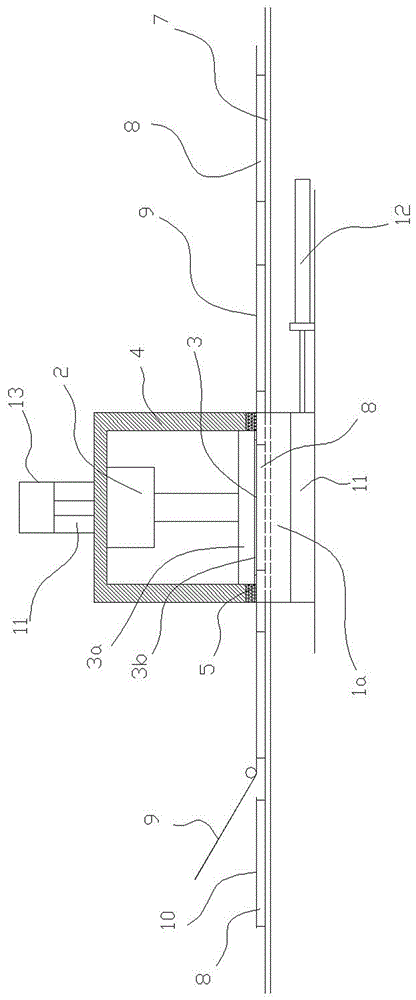
[0017] Such as image 3 As shown, the base 1 is two slats 1a and is located on both sides of the conveyor belt 7, and a recessed area 14 is formed between the two slats 1a (not shown in the figure due to the occlusion of the slats 1a), so that The mosaic tiles 8 on the conveyor belt 7 pass through, and the pap...


PUM


Abstract

A paper clipping and shaping device is characterized by comprising a base and a clipping head located on the base and driven by power to move up and down, and the clipping head comprises a pedestal and an annular electric heating wire horizontally arranged below the pedestal. Compared with the prior art, the paper clipping and shaping device has the beneficial effects of being high in cutting efficiency, low in manufacturing and using cost and high in cutting reliability.

Description

Technical field: [0001] The invention relates to a cutting technology. Background technique: [0002] The existing paper cutting technology generally adopts the knife cutting technology, which uses a cutter to cut the paper. This cutting technology is more effective for cutting the paper in sections. However, if you want to cut the paper from the Cut a piece of paper out of the middle of the paper, because the cutting knives are yin and yang knives, first, it is not easy to manufacture a knife with the same shape as the cut paper, even if it can be manufactured, the cost of manufacturing and use is also high It is very high, and once the cutter is worn out, it is not easy to restore the sharpness of the cutter by grinding. If multiple cutters are combined to form a combined cutter with the same shape as the cut paper , The gap formed between the cutters is not easy to solve, and the existence of the gap makes it impossible to completely cut the paper. Invention content: ...

Claims


Application Information

Patent Timeline
Patent Type & Authority Applications(China)
IPC IPC(8): B26F3/12
CPCB26F3/12
Inventor 王兴波田英
Owner FOSHAN UNIVERSITY
Learn More