A beam type polar coordinate 3D printer

A technology of 3D printers and polar coordinates, applied in processing drive devices, additive processing, etc., can solve problems such as the inability to guarantee Z-axis accuracy, increase the difficulty of programming control, and the direction of difficult consumables, etc., to achieve easy editing, fast printing speed, curved surface The effect of high dimensional accuracy

Active Publication Date: 2017-11-28
WUHU HIT ROBOT TECH RES INST
View PDF2 Cites 0 Cited by
  • Summary
  • Abstract
  • Description
  • Claims
  • Application Information

AI Technical Summary

Problems solved by technology

This invention is also processed in the form of polar coordinates, which is conducive to printing rotary parts, but its Z-axis is controlled by a linear connecting rod, which cannot guarantee the accuracy of the Z-axis, and it is difficult to determine the direction of the consumables, and its movement cannot be calibrated at the beginning, and its Motion is also relative motion, programming control is more difficult

Method used


Image

  • A beam type polar coordinate 3D printer
  • A beam type polar coordinate 3D printer
  • A beam type polar coordinate 3D printer

Examples


Embodiment Construction

[0030] In order to make the technical means, creative features, goals and effects achieved by the present invention easy to understand, the present invention will be further elaborated below.

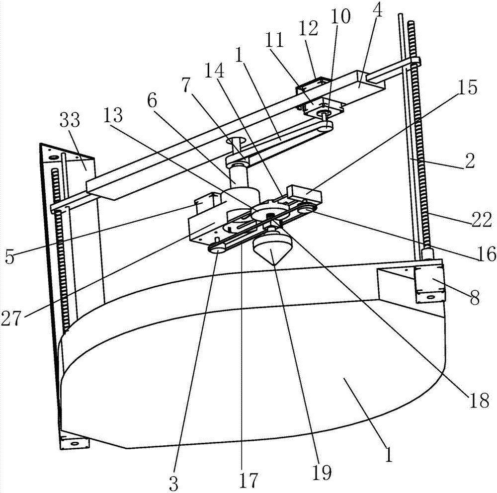
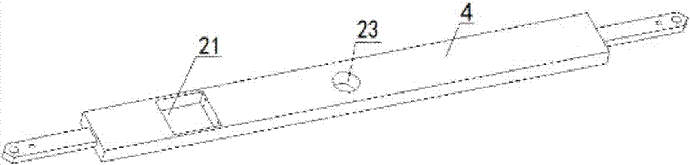
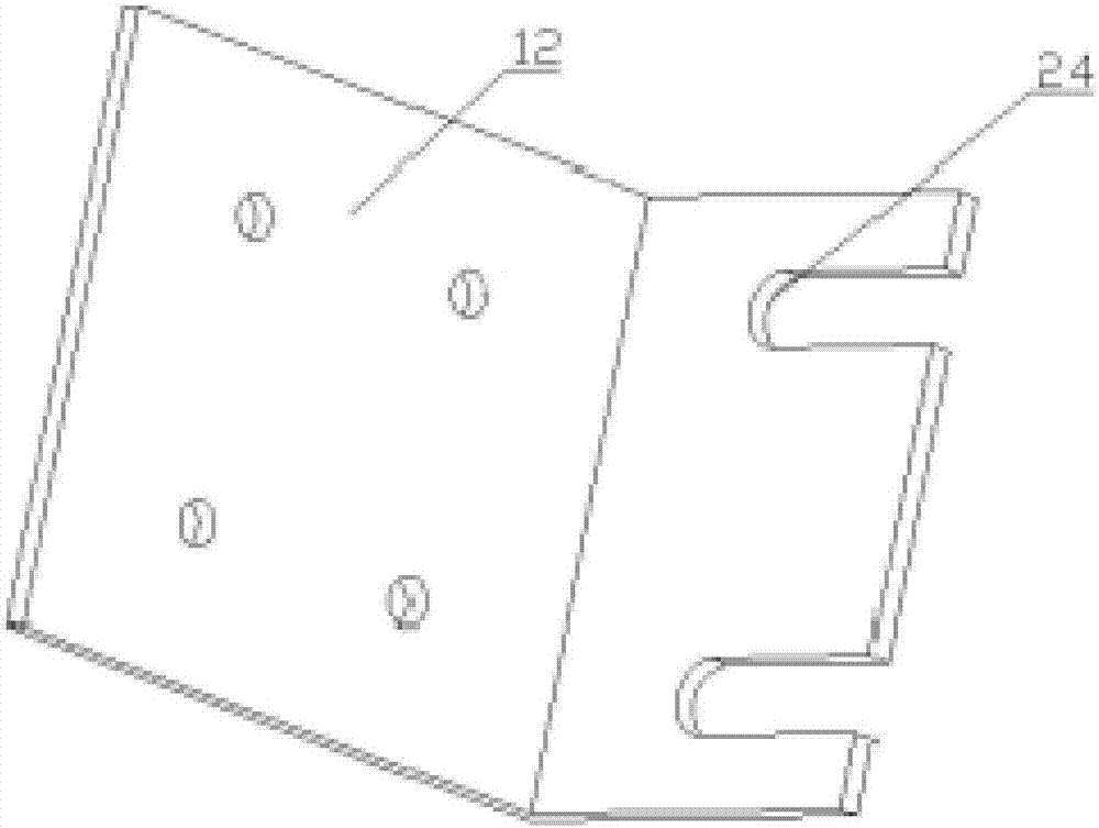
[0031] Such as Figure 1 to Figure 10 As shown, a beam-type polar coordinate 3D printer includes a base 1, a vertical shaft 2 is fixed on the left and right sides of the base 1, and a side motor is fixed on the left and right sides of the base 1 respectively. 8. A bolt rod 22 is respectively installed on the shaft of the side motor 8 through a coupling, and the bolt rods 22 are respectively parallel to the vertical shaft 2 on the corresponding side, and the upper part of the vertical shaft 2 is connected to the bolt rod 22 A crossbeam 4 is installed on the top of each other, the left side of the crossbeam 4 is provided with a square through hole 21, the middle side of the crossbeam 4 is provided with a central hole 23, the square through hole 21 is equipped with a bending part 12, and t...


PUM


Abstract

The invention relates to a cross beam type polar coordinate 3D printer. The cross beam type polar coordinate 3D printer comprises a base, the left side and the right side of the base are each fixedly provided with a vertical shaft, and the left side and the right side of the base are each fixedly provided with a side motor; shafts of the side motors are each provided with a bolt rod through a coupler; the bolt rods are parallel to the vertical shafts on the corresponding sides, and a cross beam is jointly mounted on the upper portions of the vertical shafts and the upper portions of the bolt rods; a square through hole is formed in the left side of the cross beam, and a center hole is formed in the middle side of the cross beam; a bending part is mounted in the square through hole, and a first motor is mounted on the bending part; an angle driving wheel is connected to a shaft of the first motor, and a rotating shaft is mounted in the center hole; and an angle driven wheel is mounted on the lower portion of the rotating shaft in a key connection manner, and a first conveying belt is connected between the angle driving wheel and the angle driven wheel. Drawing of a complex curve arc is achieved, the printer has the beneficial effects that the printing speed is high, the precision of the size of a printed curve is high, and the surface quality is good, the automation degree is high, and the production efficiency can be greatly improved.

Description

technical field [0001] The invention relates to the technical field of three-dimensional additive manufacturing, in particular to a beam-type polar coordinate 3D printer. Background technique [0002] Normally, the movement of a Cartesian coordinate 3D printer in a plane basically depends on the rotation of the x and y axis motors. When moving a straight line, the plane coordinates can meet the requirements well, but it needs to move a circular trajectory. At the same time, the Cartesian coordinate system is basically completed by the difference method, which is to divide a circular arc into many straight lines to simulate the curve. Generally, it is completed by controlling the x and y directions of the motor, so the efficiency of executing circular arc segments is very low and the speed is very low. slow. But if the motion mechanism of polar coordinates is used, the polar diameter ρ can be fixed, and the θ rotation angle can be controlled to obtain a smooth arc-shaped tra...

Claims


Application Information

Patent Timeline
Patent Type & Authority Patents(China)
IPC IPC(8): B29C64/20B29C64/227B33Y30/00
CPCB33Y30/00
Inventor 郭龙万立浩胡飞金力陈双范冬林
Owner WUHU HIT ROBOT TECH RES INST
Why Eureka
Try Eureka