Oil tank upper shell for hydraulic retarder

A technology of hydraulic retarder and oil tank, which is applied to transmission parts, belts/chains/gears, mechanical equipment, etc., can solve the problems of air leakage into the working chamber and affect the work of hydraulic retarder, and achieve improvement The effect of job reliability

Active Publication Date: 2018-08-10
NINGBO HUASHENG COMBINED BRAKE TECH CO LTD
View PDF5 Cites 0 Cited by
  • Summary
  • Abstract
  • Description
  • Claims
  • Application Information

AI Technical Summary

Problems solved by technology

When the oil in the fuel tank is pressed into the working chamber by the high-pressure air, the hydraulic retarder will work. When the high-pressure air in the fuel tank is discharged, the oil will flow back into the fuel tank and the hydraulic retarder will stop working, while the hydraulic retarder in the prior art When the oil tank for the hydraulic retarder is insufficient, part of the air will leak into the working chamber, which will affect the work of the hydraulic retarder

Method used


Image

  • Oil tank upper shell for hydraulic retarder
  • Oil tank upper shell for hydraulic retarder

Examples


Embodiment Construction

[0014] The present invention will be further described below in conjunction with the accompanying drawings and specific embodiments.

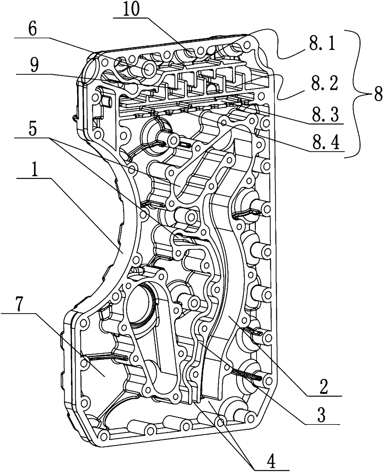
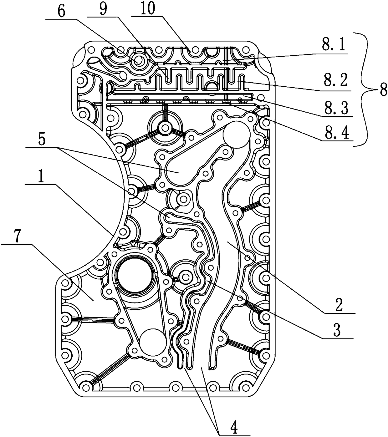
[0015] The invention provides an oil tank upper casing for a hydraulic retarder, which includes a casing body 1, and is characterized in that: the casing body 1 is provided with a main oil passage 2 and an auxiliary oil passage 3, and the main oil passage 2 and the auxiliary oil passage The lower ends of 3 are respectively provided with oil inlets 4 communicating with the inner cavity of the shell body 1, and the upper ends of the main oil passage 2 and auxiliary oil passage 3 are respectively provided with oil outlets 5 connected with the working area. The upper part is provided with an air inlet 6 for supplying high-pressure air in the inner cavity of the shell body 1. The high-pressure air drives the oil in the shell body 1 to be pressed into the working area through the main oil passage 2 and the auxiliary oil passage 2. There is an oil sto...


PUM


Abstract

The invention discloses an oil tank upper shell for a hydraulic retarder. The oil tank upper shell comprises a shell body. The oil tank upper shell is characterized in that a main oil duct and a secondary oil duct are arranged in the shell body, oil inlets which are communicated with an inner cavity of the shell body are respectively formed in the lower ends of the main oil duct and the secondary oil duct, oil outlets which are communicated with a working area are respectively formed in the upper ends of the main oil duct and the secondary oil duct, an air inlet which is used for supplying high-pressure air to the inner cavity of the shell body is formed in the upper part of the shell body, oil in the shell body is driven by the high-pressure air to enter the working area through the main oil duct and the secondary oil duct, an oil storage chamber with a downward opening is formed in the shell body, and the horizontal plane on which the highest point of the opening of the oil storage chamber is positioned is higher than that on which the highest point of the oil inlets of the main oil duct and the secondary oil duct is positioned. According to the oil tank upper shell for the hydraulic retarder, air which enters a working chamber from an oil tank can be reduced, so that the reliability of the hydraulic retarder is increased.

Description

technical field [0001] The invention relates to the technical field of a hydraulic retarder, in particular to an upper casing of an oil tank for a hydraulic retarder. Background technique [0002] The hydraulic retarder is a reducer for large trucks. It converts the kinetic energy of the transmission shaft into the internal energy of the oil through the agitation of the oil, and then dissipates heat through the heat exchanger to achieve the retarding effect. When the oil in the fuel tank is pressed into the working chamber by the high-pressure air, the hydraulic retarder works, and when the high-pressure air in the fuel tank is discharged, the oil returns to the hydraulic retarder in the fuel tank to stop working, while the hydraulic retarder in the prior art When the oil tank for the hydraulic retarder is insufficient, part of the air will leak into the working chamber, which will affect the work of the hydraulic retarder. Contents of the invention [0003] The technical...

Claims


Application Information

Patent Timeline
Patent Type & Authority Patents(China)
IPC IPC(8): F16H57/04F16H57/00
CPCF16H57/00F16H57/045
Inventor 陈江波姚峰王媛媛
Owner NINGBO HUASHENG COMBINED BRAKE TECH CO LTD
Why Eureka
Try Eureka