Cycloid steel ball planetary reducer gap elimination mechanism

A technology of planetary reducer and cycloidal steel ball, which is applied in the direction of mechanical equipment, transmission parts, belt/chain/gear, etc. It can solve the problems of large frictional resistance of planetary disk, decreased transmission performance, and inability to realize axial force output, etc. , to achieve the effects of small axial movement resistance, elimination of backlash and small frictional resistance

Inactive Publication Date: 2017-12-29
YANSHAN UNIV
View PDF5 Cites 0 Cited by
  • Summary
  • Abstract
  • Description
  • Claims
  • Application Information

AI Technical Summary

Problems solved by technology

After the modern high-precision transmission mechanism wears out, there will be backlash on the tooth side, and its transmission performance will inevitably decline. Only a momentary backlash-free meshing transmission can no longer meet the requirements of the precision transmission mechanism for transmission accuracy.
The cycloidal ball planetary reducer has a stage clearance elimination mechanism that cannot achieve continuous elimination of the tooth side clearance, and a stepless clearance elimination mechanism cannot achieve a constant axial force output, and the axial movement of the planetary disk is subject to greater frictional resistance

Method used


Image

  • Cycloid steel ball planetary reducer gap elimination mechanism
  • Cycloid steel ball planetary reducer gap elimination mechanism
  • Cycloid steel ball planetary reducer gap elimination mechanism

Examples


Embodiment Construction

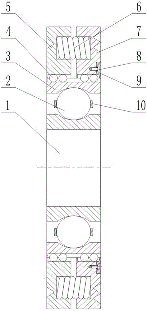
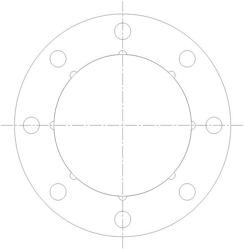
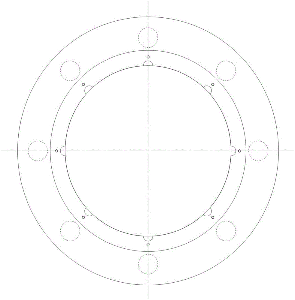
[0012] exist figure 1 , figure 2 and image 3 In the schematic diagram of the present invention shown, the outer part of the inner ring 1 is provided with a cage 10, the cross section of the cage is circular, and a number of ball pockets are provided on the cage, and the steel ball A2 is placed in the cage The inside of the ball pocket. The outer ring 3 is sleeved on the outside of the cage. Eight rolling grooves are arranged on the outer side of the outer ring, and baffle plates are arranged at one end of the rolling grooves on the outer side of the outer ring. Both the inner rings of the movable disc A5 and the inner rings of the movable disc B7 are provided with 8 rolling grooves, and the inner rings of the movable disc A and the movable disc B are provided with baffles at one end of the rolling grooves. The rolling grooves on the outer side of the outer ring correspond to the rolling grooves on the inner rings of the movable disc A and the movable disc B one by one, f...


PUM


Abstract

The invention discloses a cycloid steel ball planetary reducer interval removing mechanism. A cage is arranged out of an inner ring; a steel ball A is positioned in the cage; the external of the cage is sleeved with an outer ring; a rolling groove is formed in the outer side of the outer ring; a baffle plate is arranged at one end of the rolling groove in the outer side of the outer ring; rolling grooves are respectively formed in an inner ring of a mobile disc A and an inner ring of a mobile disc B; baffle plates are respectively arranged at one ends of the rolling grooves in the inner rings of the mobile disc A and the mobile disc B; the rolling groove in the outer side of the outer ring and the rolling grooves in the inner rings of the mobile disc A and the mobile disc B form a combined rolling groove; a steel ball B is arranged in the combined rolling groove; groove holes are formed in the inner sides of the mobile disc A and the mobile disc B; springs are respectively arranged in the groove holes; a thread hole is formed in the outer side of the mobile disc B; a through hole is formed in a retainer ring; and the retainer ring is fixed on the outer side of the mobile disc B through a screw. The cycloid steel ball planetary reducer interval removing mechanism is simple and compact in structure, adopts gapless transmission, and can continuously remove side intervals of engagement pair teeth; the discs axially move through the steel ball in the combined groove; and the steel ball and a chute are contacted in a rolling manner, so that the friction resistance is low, and the axial movement resistance of each disc is low.

Description

technical field [0001] The invention relates to the technical field of mechanical transmission, in particular to a clearance elimination mechanism of a reducer. Background technique [0002] The reducer is an important part of the machinery industry, and its transmission performance directly affects the production efficiency, work performance and product quality of the machinery. After the modern high-precision transmission mechanism wears out, there will be backlash on the tooth side, and its transmission performance will inevitably decline. Only having a backlash-free meshing transmission for a while can no longer meet the requirements of the precision transmission mechanism for transmission accuracy. Cycloidal steel ball planetary reducer has a stage clearance elimination mechanism that cannot realize continuous elimination of tooth side clearance, and a stepless clearance elimination mechanism cannot achieve constant axial force output, and the axial movement of the plan...

Claims


Application Information

Patent Timeline
Patent Type & Authority Patents(China)
IPC IPC(8): F16H57/12
CPCF16H57/12F16H2057/127
Inventor 安子军杨荣刚
Owner YANSHAN UNIV
Why Eureka
Try Eureka