Flange instrument valve sealing testing device

A technology of valve sealing and testing equipment, which is applied in the direction of fluid tightness testing, measuring equipment, and testing of machine/structural components, etc. It can solve problems such as affecting test results, taking a long time, and scrapping flanged instrument valves.

Active Publication Date: 2016-06-22
FUJIAN WIDE PLUS PRECISION INSTR
View PDF10 Cites 3 Cited by
  • Summary
  • Abstract
  • Description
  • Claims
  • Application Information

AI Technical Summary

Problems solved by technology

However, in the prior art, because the flange instrument valve needs to repeatedly disassemble and assemble the end cover, repeatedly tighten bolts, screws and other fasteners during the shell strength test and sealing test process, the workload is heavy, and it often takes a lot of time. Low work efficiency, long production cycle, and improper operation, or inaccurate positioning of the movable clamp seat by bolts, screws and other fasteners, resulting in poor sealing of the inlet and outlet of the instrument valve, which will affect the test results. It is also easy to bruise and damage the inlet and outlet of the flange instrument valve, and even cause adverse consequences such as scrapping the flange instrument valve.

Method used


Image

  • Flange instrument valve sealing testing device
  • Flange instrument valve sealing testing device
  • Flange instrument valve sealing testing device

Examples


Embodiment 1

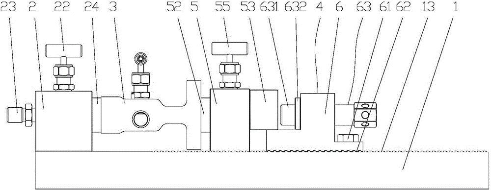
[0039] Such as Figure 5 As shown, when testing the single inlet and outlet flange instrument valve 31, a set of flange instrument valve sealing test device of the present invention is used to connect the inlet and outlet of the single inlet and outlet flange instrument valve 31 to the second sealing cover assembly 24 respectively. The second through hole on the top is communicated with the first through hole on the first sealing cover assembly 52, and then the movable clamp seat 4 is used to tighten and seal.

Embodiment 2

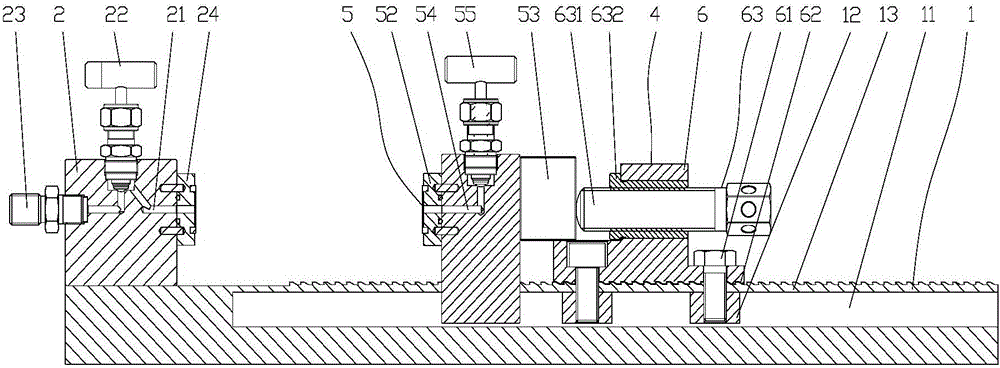
[0041] Such as Image 6 As shown, when testing the double inlet and outlet flange instrument valve 32, two sets of flange instrument valve sealing test devices of the present invention are used. The two sets of flange instrument valve seal test devices have two bases 1, and the two ends of the two bases 1 are Each is connected by a connecting piece 7 to form a whole, and then the two inlets of the double inlet and outlet flange instrument valve 32 are respectively communicated with the second through holes on the two second sealing cover assemblies 24, and the double inlet and outlet method The two outlets of the blue meter valve 32 communicate with the first through holes on the two first sealing cover assemblies 52 respectively, and then respectively go through the two movable clip seats 4 to tighten and seal.

[0042] The present invention adopts the above technical scheme. When installing the flange instrument valve 3 to be tested, the T-shaped part 51 of the movable suppo...


PUM


Abstract

The invention relates to a flange instrument valve sealing testing device which comprises a base. A stationary clamp seat which is internally provided with a pressure conveying channel is fixedly arranged at one end of the base. The other end of the vase is provided with a movable clamping seat. The base is provided with a T-shaped rail. At least one T-shaped slide block is embedded into the T-shaped rail. The upper surface of the base is provided with a sawtooth-shaped rail. The movable clamping seat comprises an abutting supporting seat and a movable supporting seat. The movable supporting seat is arranged between the stationary clamp seat and the abutting supporting seat. The bottom of the movable supporting seat is provided with a T-shaped part which is slidably connected with the T-shaped rail. One end of the movable supporting seat is provided with a first sealing cover assembly which is used for sealing the outlet of the instrument valve. The abutting supporting seat is connected with the T-shaped slide block through a fastener. The abutting supporting seat is fixed on the base. The lower surface of the abutting supporting seat is provided with unidirectional stopping sawteeth which are connected with the sawtooth-shaped rail, thereby preventing movement of the abutting supporting seat to the other end of the base. The abutting supporting seat is provided with a pushing mechanism which is used for pushing the movable supporting seat for making the instrument valve abut against the stationary clamp seat.

Description

technical field [0001] The invention relates to the technical field of a valve sealing test device, in particular to a flange instrument valve sealing test device. Background technique [0002] With the growth of the national economy, the demand for instrument valves in petroleum, chemical industry, electric power, metallurgy and other fields is increasing day by day, and the market has put forward higher quality requirements and shorter delivery cycles for instrument valve manufacturers. Flange instrument valves are connected to instruments and meters through flanges. After the instrument valves are produced, they must pass strict air-tightness, water-tightness and other sealing tests to ensure the quality of the instrument valves. [0003] The existing instrument valve sealing test device includes a base, and the two ends of the base are respectively provided with a static clamp seat and a dynamic clamp seat for clamping and fixing the instrument valve. The base is fixed,...

Claims


Application Information

Patent Timeline
Patent Type & Authority Applications(China)
IPC IPC(8): G01M3/08
CPCG01M3/086
Inventor 郑子文陈鹏许启鑫林毕文林仁祥黄训松
Owner FUJIAN WIDE PLUS PRECISION INSTR
Why Eureka
Try Eureka