
Engine air inlet noise sound power test system and test method thereof

A technology of intake noise and testing system, which is applied in engine testing, machine/structural component testing, and measurement of ultrasonic/sonic/infrasonic waves, etc. It can solve the problem of changing the frequency characteristics of intake noise, not reflecting intake noise, and low-frequency noise Diffraction effects and other problems occur

Active Publication Date: 2016-06-22
CHONGQING CHANGAN AUTOMOBILE CO LTD
View PDF7 Cites 7 Cited by
  • Summary
  • Abstract
  • Description
  • Claims
  • Application Information

AI Technical Summary

Problems solved by technology

[0002] At present, in the field of powertrain NVH, the method of measuring near-field sound pressure or covering with a large baffle and using an extension tube to lead out the intake air is used to evaluate the intake noise of the engine. The disadvantage is that the intake noise will be overwhelmed by other noises of the engine. The sound pressure measured in the near field cannot reflect the pure intake noise
The second disadvantage is that the production of large baffles needs to be strictly consistent with the length, width and height specifications of the anechoic chamber, otherwise once there is a gap, low-frequency noise will have diffraction effects
The third disadvantage is that adding an intake extension tube will change the frequency characteristics of the intake noise

Method used


Image

  • Engine air inlet noise sound power test system and test method thereof
  • Engine air inlet noise sound power test system and test method thereof
  • Engine air inlet noise sound power test system and test method thereof

Examples


Embodiment Construction

[0074] In order to better understand the present invention, the content of the present invention will be further explained below in conjunction with the accompanying drawings and embodiments, but the content of the present invention is not limited to the following embodiments. Those skilled in the art can make various changes or modifications to the present invention, and these equivalent forms are also within the scope of the claims listed in this application.

[0075] Below take the intake noise of a certain type of engine on the engine stand to adopt the present invention to test and analyze as an example:

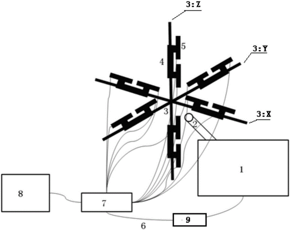
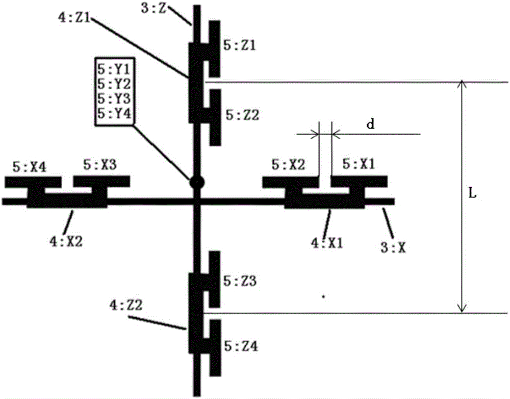
[0076] Such as figure 1 and figure 2 As shown, the test system includes: 12 microphones 5, 6 fixtures 4, microphone mounting bracket 3, tachometer 9, data acquisition equipment 7, PC computer 8 and several BNC wiring harnesses 6.

[0077] System design key include:

[0078] 1. The assembly design of the sound intensity probe: there are 12 microphones 5, marked X1, X...


PUM


Abstract

The invention provides a test system of measuring engine air inlet noise sound power and a method thereof. In the invention, assembling of an installation support and a sound intensity probe is specially designed. The test system is constructed, and a scientific sound intensity and sound power algorithm is used to process a test signal. Through using a characteristic that a sound intensity vector carries out integral along a closed curved surface, an engine air inlet noise is completely isolated and extracted from an integral and complex noise field of an engine mathematically so as to be served as a reliable basis of evaluating the engine air inlet noise. Compared to sound power measurement by using an existing traditional sound pressure method, by using the method in the invention, a test result is irrelevant with a peripheral sound field, which means that there is no requirement to a sound field test environment and the test does not need to be performed in a specific acoustic environment, such as an anechoic chamber and a live room. Based on a mathematics principle, a characteristic of an air inlet noise source can be extracted from the complex engine noise field. Tool equipment, such as a big barrier board, an air inlet extension tube and the like, does not need to be designed and made.

Description

technical field [0001] The invention belongs to the technical field of engines, and in particular relates to an engine air inlet noise sound power testing system and a testing method thereof. Background technique [0002] At present, in the field of powertrain NVH, the method of measuring near-field sound pressure or covering with a large baffle and using an extension tube to lead out the intake air is used to evaluate the intake noise of the engine. The disadvantage is that the intake noise will be overwhelmed by other noises of the engine. The sound pressure measured in the near field also cannot reflect the pure intake noise. The second disadvantage is that the production of large baffles needs to be strictly consistent with the length, width and height specifications of the anechoic chamber, otherwise once there is a gap, low-frequency noise will have diffraction effects. The third disadvantage is that adding an intake extension tube will change the frequency characteri...

Claims


Application Information

Patent Timeline
IPC IPC(8): G01M15/00G01H17/00
CPCG01H17/00G01M15/00
Inventor 邵俊龙闻刚杨金才刘刚陈文俊
Owner CHONGQING CHANGAN AUTOMOBILE CO LTD
Learn More