Measuring method for environment surface reflectivity spectrum in visible light diffusion communication
A measurement method and environmental technology, applied in the field of wireless optical communication, can solve the problem of inability to obtain the reflectivity of reflective materials, and achieve the effect of improving measurement efficiency
- Summary
- Abstract
- Description
- Claims
- Application Information
AI Technical Summary
Problems solved by technology
Method used
Image

Examples
Embodiment Construction
[0034] The technical solutions in the embodiments of the present invention will be clearly and completely described below in conjunction with the accompanying drawings in the embodiments of the present invention. Obviously, the described embodiments are only some of the embodiments of the present invention, not all of them. Based on the embodiments of the present invention, all other embodiments obtained by persons of ordinary skill in the art without making creative efforts belong to the protection scope of the present invention.
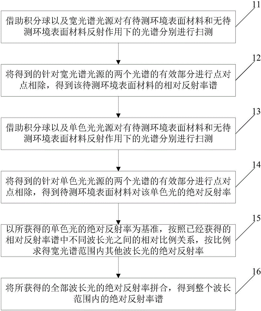
[0035] Embodiments of the present invention will be further described in detail below in conjunction with the accompanying drawings, as figure 1 Shown is a schematic flowchart of a method for measuring the reflectance spectrum of an environmental surface in diffuse visible light communication provided by an embodiment of the present invention, and the method includes:
[0036] Step 11: Using the integrating sphere and the wide-spectrum light source...
PUM
 Abstract
Description
Claims
Application Information