Novel pressure injection mold

A mold and a new type of technology, applied in the direction of commutator manufacturing, etc., can solve problems such as production waste, achieve the effects of reducing costs, reducing waste, and increasing utilization

Inactive Publication Date: 2016-06-22
贺广民
View PDF0 Cites 0 Cited by
  • Summary
  • Abstract
  • Description
  • Claims
  • Application Information

AI Technical Summary

Problems solved by technology

[0003] The production of commutator is generally made by mold injection. In conventional injection molds, the bakelite powder is directly pressed into the material chamber by the pressing block, so that the bakelite powder enters the product cavity through the injection port under high pressure and high temper

Method used


Image

  • Novel pressure injection mold
  • Novel pressure injection mold

Examples


Embodiment Construction

[0014] The following will clearly and completely describe the technical solutions in the embodiments of the present invention with reference to the drawings in the embodiments of the present invention.

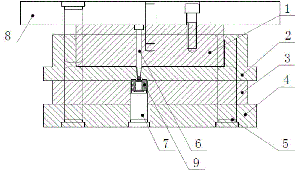
[0015] Such as figure 2 As shown, a new type of injection mold includes a guide post 5, a mounting plate 8, a material block 1, a material chamber 2, a middle mold 3, a lower mold 7 and a lower mold fixing plate 4, and the material block 1 is provided with a series of The main material hole, each of the main material holes is embedded with a guide nail 6, and the lower end of the guide nail 6 is placed in the material chamber 2.

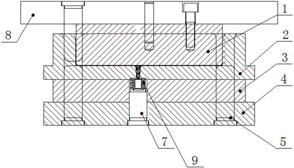
[0016] Compared figure 1 The existing injection mold shown, a new type of injection mold provided by the present invention, reduces the waste of each main material hole by embedding guide nails 6 in the main material holes. Extrusion filling makes the flow speed of bakelite powder faster, and the thickness of the waste left in the bottom layer of ...


PUM


Abstract

The invention discloses a novel pressure injection mold. The novel pressure injection mold includes a guide column, a mounting plate, a material block, a material chamber, a lower mold and a lower mold fixing plate; a series of main material holes are formed in the material block; a guide screw is inserted in each main material hole; and the lower end of each guide screw is arranged in the material chamber. The novel pressure injection mold provided by the invention is applied to the production manufacture of commutators and can assist in improving production efficiency and product profits.

Description

technical field [0001] The invention relates to the field of electric appliance manufacturing, in particular to a novel injection mold for manufacturing commutators. Background technique [0002] The commutator, commonly known as the commutator, is a part of the DC permanent magnet series (single-phase AC series) motor to allow the motor to continue to rotate. It is widely used in electric tools, household appliances, and automotive motors. [0003] The production of commutator is generally made by mold injection. In conventional injection molds, the bakelite powder is directly pressed into the material chamber by the pressing block, so that the bakelite powder enters the product cavity through the injection port under high pressure and high temperature. In order to ensure that the product does not The density of the internal tissue structure of the air hole and pressure injection meets the requirements. After the product is formed, a layer of waste material with a thickness...

Claims


Application Information

Patent Timeline
IPC IPC(8): H01R43/06
Inventor 贺广民
Owner 贺广民
Why Eureka
Try Eureka