Inrush current limiter

A current limiter and current control technology, which is applied in the direction of only measuring current, electrical components, circuit devices, etc., can solve problems such as operation failure and fuse blown

Active Publication Date: 2016-06-22
NXP BV
View PDF3 Cites 0 Cited by
  • Summary
  • Abstract
  • Description
  • Claims
  • Application Information

AI Technical Summary

Problems solved by technology

After repeated operations, the fuse may "blow", which causes the operation to fail
Therefore, such fuses may have to

Method used


Image

  • Inrush current limiter
  • Inrush current limiter
  • Inrush current limiter

Examples


Embodiment Construction

[0018] The description and drawings illustrate the principles of the invention. It will be appreciated that those skilled in the art can devise various specific arrangements that incorporate the principles of the present application within the scope of the application, although such specific arrangements are not explicitly described or shown herein. In addition, all the examples recorded here are mainly for the purpose of teaching to help readers understand the principle of the present invention and the ideas contributed by the inventors in technical progress, and it is not intended to be limited to these specific recorded embodiments and conditions. In addition, the term "or" as used herein means non-exclusive (ie, and / or), unless otherwise indicated (eg, "otherwise" or "or alternatively"). The various embodiments described herein are not necessarily mutually exclusive, as some embodiments can be combined with one or more other embodiments to form new embodiments. As used he...


PUM


Abstract

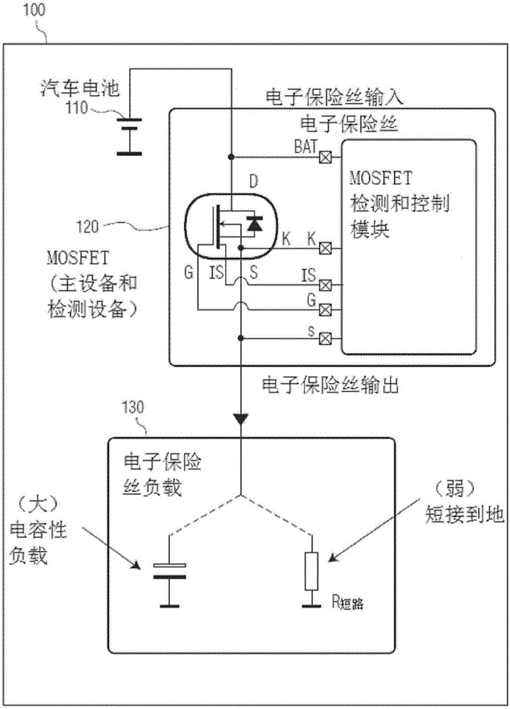
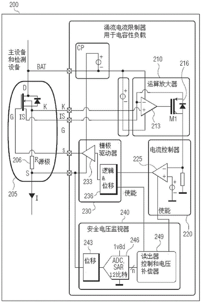
An inrush current limiter for electronic fuses detects the type of load connected to the electronic fuse at ignition. By detecting the type of load, the limiter prevents a large peak current from flowing through the fuse. When a short circuit occurs, the limiter ensures that the electronic fuse only operates once in linear mode.

Description

technical field [0001] Various embodiments of the invention generally relate to limiting inrush current. Background technique [0002] Fuses are commonly used to protect wires and electrical equipment from excessive current flow. Fuses are especially required for vehicles, such as automobiles. In various automobiles and trucks, blade type, Bosch type, Lucas type, glass tube type, and limiter type fuses have been used. [0003] When such fuses operate, they may "trip" when a hazardous situation occurs. After repeated operations, the fuse may "blow", which causes the operation to fail. Therefore, such fuses may have to be replaced periodically, as a "blown fuse" will cause some components in the vehicle to no longer function properly. Contents of the invention [0004] Various embodiments are briefly summarized below. Some simplifications and omissions may be made in the following summary of the invention, the purpose of which is to emphasize and introduce some aspects ...

Claims


Application Information

Patent Timeline
IPC IPC(8): H02H9/02
CPCG01R19/0092H02H1/0007H02H9/001H02H9/025
Inventor 鲁克·范戴克
Owner NXP BV
Why Eureka
Try Eureka