Catalyst continuous reducing apparatus and method

A catalyst and conveying channel technology, applied in the field of coal chemical industry, can solve the problems of complex operation, high solid content of the final liquid product, and reduce the solid content of the final liquid product, and achieve the effect of simple operation, avoiding wear and continuous reduction

Active Publication Date: 2016-06-29
CHNA ENERGY INVESTMENT CORP LTD +1
View PDF7 Cites 5 Cited by
  • Summary
  • Abstract
  • Description
  • Claims
  • Application Information

AI Technical Summary

Problems solved by technology

[0006] The purpose of the present invention is to overcome the shortcomings of complex operation and high solid content of the final liquid product in the existing technology for reducing Fischer-Tropsch synthesis catalysts, and provide a device and method capable of continuous operation and reducing the solid content of the final liquid product

Method used


Image

  • Catalyst continuous reducing apparatus and method
  • Catalyst continuous reducing apparatus and method

Examples


Embodiment 1

[0066] This example is used to illustrate the catalyst continuous reduction device and the reduction method of the iron-based Fischer-Tropsch synthesis catalyst of the present invention.

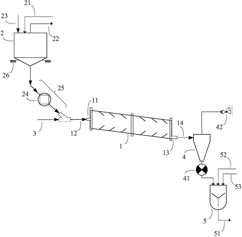
[0067] refer to figure 1 , the iron-based Fischer-Tropsch synthesis catalyst to be reduced is added in the storage tank 2 through the catalyst inlet 23 arranged on the storage tank 2, wherein the storage tank 2 also has a catalyst outlet 20; the catalyst outlet 20 is connected to the rotary reactor A sealed catalyst delivery channel 25 is provided between the feed ports 11 of the reactor 1; the sealed catalyst delivery channel 25 communicates with the feed port 11 of the rotary reactor 1 in a dynamic seal. Wherein the storage tank 2 is provided with a first inert gas inlet 21, a vacuum suction port 22 and a weighing scale 26; the effect of the weighing scale 26 is to measure the quality of the catalyst entering the reduction reactor; The gas brought in by the catalyst is introduced into the...

Embodiment 2

[0075] This example is used to illustrate the reduction method of cobalt-based Fischer-Tropsch synthesis catalyst.

[0076] The device and method of Example 1 were used to reduce the catalyst, except that the catalyst to be reduced was the cobalt-based Fischer-Tropsch synthesis catalyst as described above. And among them, the reducing gas is H 2 , the temperature in the rotary reactor 1 is 400°C, the pressure is 1MPa, and the volume space velocity of the reducing gas is 10000h -1 , the reduction time of the catalyst is 24h; the volume of the catalyst accounts for 10% by volume of the volume of the rotary reactor 1; the rotating speed of the rotary reactor 1 is 5 rpm; the aspect ratio of the rotary reactor 1 is 50:1. The reduced cobalt-based Fischer-Tropsch synthesis catalyst of this embodiment is obtained through reduction.


PUM

PropertyMeasurementUnit
particle diameteraaaaaaaaaa
particle sizeaaaaaaaaaa
particle diameteraaaaaaaaaa

Abstract

The present invention provides a catalyst continuous reducing apparatus which comprises at least one storage tank, a reducing gas conveying pipeline, a rotary reactor, a gas-solid separator and a receiving tank. The present invention also provides a catalyst continuous reducing method comprising: (a) mixing a to-be-reduced catalyst with a reducing gas to obtain a first mixed material; (b) introducing the first mixed material into the rotary reactor for reduction under rotary conditions to obtain a second mixed material containing a reduced product; (c) leading the second mixed material out from a material outlet to the gas-solid separator for gas-solid separation; and leading a separated solid, by a solid material end of the gas-solid separator, into the receiving tank, and mixing the separated solid with a liquid medium in the receiving tank. The catalyst continuous reducing apparatus can achieve continuous reduction of the catalyst, the operation is simple, and the catalyst continuous reducing apparatus can avoid solid catalyst attrition in the reduction process so as to reduce content of a final liquid product.

Description

technical field [0001] The invention relates to the field of coal chemical industry, in particular to a device for continuously reducing catalysts and a method for continuously reducing catalysts. Background technique [0002] Fischer-Tropsch synthesis refers to the process of synthesizing paraffin-based liquid fuels with synthesis gas as raw material under catalyst and appropriate reaction conditions. It is one of the indirect coal liquefaction technologies. Fischer-Tropsch synthesis was developed by German chemists F. Fischer and H. Tropsch in 1923. At present, the light engine fuel produced by Fischer-Tropsch synthesis using coal as raw material cannot be compared with petroleum products economically. However, Fischer-Tropsch synthesis has great application value for solving the needs of engine fuels in countries or regions with rich and cheap coal resources but poor oil resources. [0003] The overall technological process of Fischer-Tropsch synthesis mainly includes co...

Claims


Application Information

Patent Timeline
Patent Type & Authority Applications(China)
IPC IPC(8): B01J37/18B01J23/78B01J23/80C10G2/00
Inventor 朱加清罗明生石玉林吕毅军程萌常海
Owner CHNA ENERGY INVESTMENT CORP LTD
Why Eureka
Try Eureka