Automatic gluing mechanism

A gluing, automatic technology, applied in the direction of coating, the device for applying liquid to the surface, etc., can solve the problems of the gluing rod inserted outside the catheter or the end face of the catheter, the work efficiency is low, and the gluing cannot be normally applied. The effect of better gluing effect, rapid response, and higher qualification rate

Active Publication Date: 2016-06-29
YANTAI KAIBO AUTOMATION TECH
View PDF7 Cites 7 Cited by
  • Summary
  • Abstract
  • Description
  • Claims
  • Application Information

AI Technical Summary

Problems solved by technology

Although this kind of gluing device also achieves the effect of automatic gluing, when gluing, the medical accessories and the gluing rod move relatively. If the gluing rod and the medical accessories such as the catheter port are facing each other, then the gluing rod is inserted normally. By rotating the gluing rod, the inner wall of the catheter can be evenly coated; if the gluing rod is not aligned with the medical accessories, the gluing rod will be inserted outside the catheter or the end surface of the catheter, so that the glue cannot be applied normally
[0003] The patent number is 2012101832928, the invention patent application for the glue application method and device of medical infusion set components, which discloses that the liquid level of the glue cup is controlled by a solenoid valve, and the slider seat and glue dispensing rod are controlled by a cylinder to realize automatic glue application. Compared with manual gluing, this kind of gluing device only realizes automatic gluing at one station, that is, it can only work on one gluing workpiece at a time, and the work efficiency is low.

Method used


Image

  • Automatic gluing mechanism
  • Automatic gluing mechanism
  • Automatic gluing mechanism

Examples


Embodiment Construction

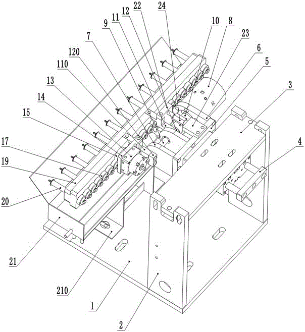
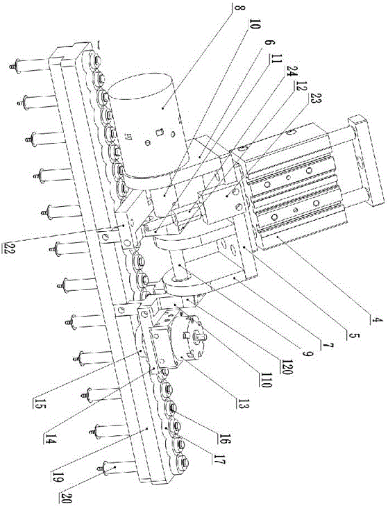
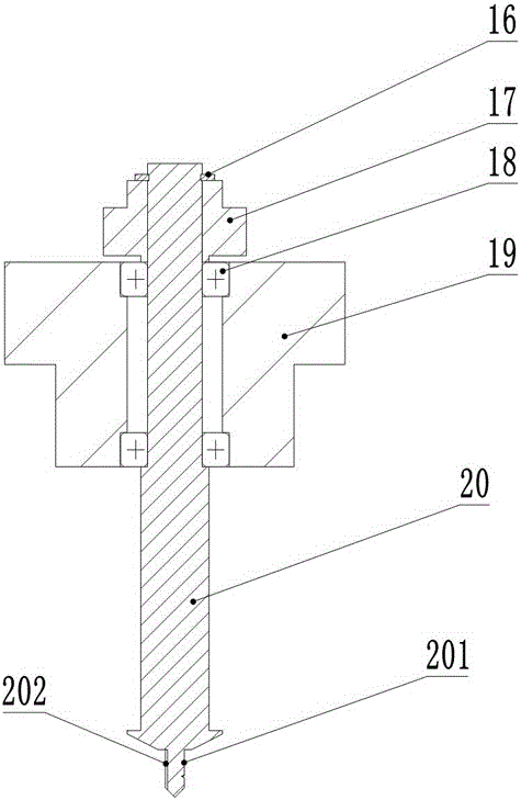
[0017] For better understanding and implementation, the present invention will be further described below in conjunction with accompanying drawing: Figure 1-4 As shown, the automatic gluing mechanism includes a gluing bottom plate 1, a gluing vertical plate 2 and a reciprocating cylinder seat 3. There are positioning grooves on both sides of the gluing bottom plate 1, and at the same time, there are positioning long grooves and two screw holes on the large surface. and four installation holes, the glued vertical plate 2 is vertically arranged on both sides of the rubberized bottom plate 1, the upper end of the glued vertical plate 2 is provided with grooves and long slotted holes, the reciprocating cylinder seat 3 is a steel plate, and both ends are provided with convex holes. The table is erected in the groove of the glue-coated vertical board 2, and fixed with screws in the long slot hole on the side of the glue-coated vertical board 2 after adjusting the height of the recip...


PUM


Abstract

The invention provides an automatic gluing mechanism which comprises a gluing bottom plate. A gluing vertical plate and a glue box support are arranged on the gluing bottom plate. A glue box is arranged on the glue box support. A reciprocating air cylinder seat is arranged on the gluing vertical plate. A reciprocating air cylinder is arranged below the reciprocating air cylinder seat. A gluing base plate is arranged at the front end of the reciprocating air cylinder. A swing cylinder fixing plate is arranged on one side of the gluing base plate. A swing cylinder is arranged on one side of the swing cylinder fixing plate. A swing cylinder shaft of the swing cylinder penetrates a through hole in the swing cylinder fixing plate, and the other side and the middle portion of the gluing base plate are each provided with a bearing seat plate. A gluing shaft is arranged between the bearing seat plates. One end of the gluing shaft is connected with the swing cylinder shaft of the swing cylinder through a coupler. One bearing seat plate is provided with a cylinder swinging clamp A, and the other bearing seat plate is provided with a cylinder swinging clamp B. Multiple stations are adopted for simultaneous work, the production efficiency is greatly improved, an air cylinder driving manner is adopted so that responding can be faster, the mechanism is prevented from losing control through mechanical contact limiting, and a gluing effect is better through a designed special gluing needle.

Description

[0001] The invention relates to the technical field of automatic assembly of medical products, in particular to an automatic gluing mechanism for assembling medical transfusion products. Background technique [0002] The development and progress of medical civilization and technology have driven the demand for pharmaceutical products, among which the demand for pharmaceutical storage and plastic products for infusion is growing rapidly. Most of these products are made of plastic PVC or ABS materials. During the assembly process, a layer of sealing glue needs to be applied, that is, cyclohexanone. Cyclohexanone can make the plastic material in a slightly melted state in a short period of time. The plastic is inserted at this point, which solidifies (cures) to seal and cannot be disassembled. The patent number is 2015106439892, and the title of the invention is a patent application for a gluing device for medical accessories. It discloses that the gluing device includes a mount ...

Claims


Application Information

Patent Timeline
Patent Type & Authority Applications(China)
IPC IPC(8): B05C7/02
CPCB05C7/02
Inventor 于海滨李传伟王吉明朱文广林荣俊于朝气
Owner YANTAI KAIBO AUTOMATION TECH
Why Eureka
Try Eureka