Knurl aligning device for shaft

An aligning device and knurling technology are applied in the field of shaft knurling aligning devices, which can solve the problems of low precision and cumbersome adjustment operations, and achieve the effect of improving processing efficiency and precision.

Active Publication Date: 2016-06-29
WARNER SHENGLONG NINGBO CO LTD
View PDF14 Cites 4 Cited by
  • Summary
  • Abstract
  • Description
  • Claims
  • Application Information

AI Technical Summary

Problems solved by technology

However, the knurling tool needs to manually adjust the center height between the knurling tool and the axis of the machining shaft during the knurling process of the shaft end. The adjustment operation is cumbersome and the precision is low.

Method used


Image

  • Knurl aligning device for shaft
  • Knurl aligning device for shaft
  • Knurl aligning device for shaft

Examples


Embodiment Construction

[0024] The present invention will be further described in detail below in conjunction with the accompanying drawings and embodiments.

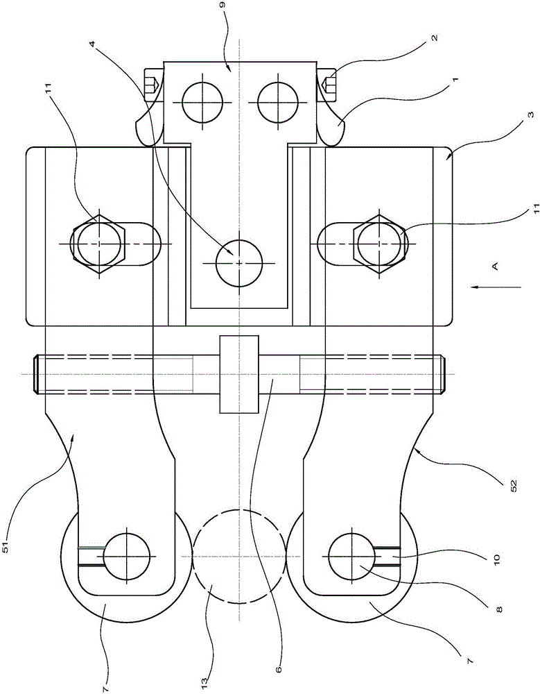
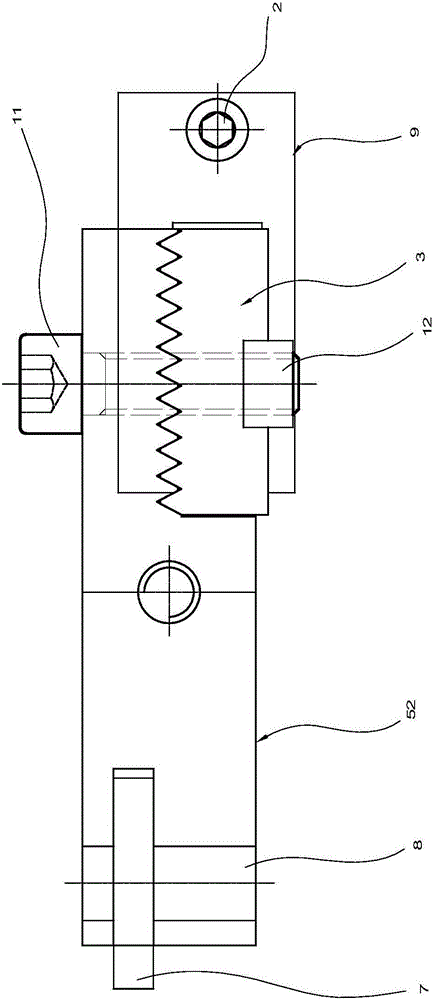
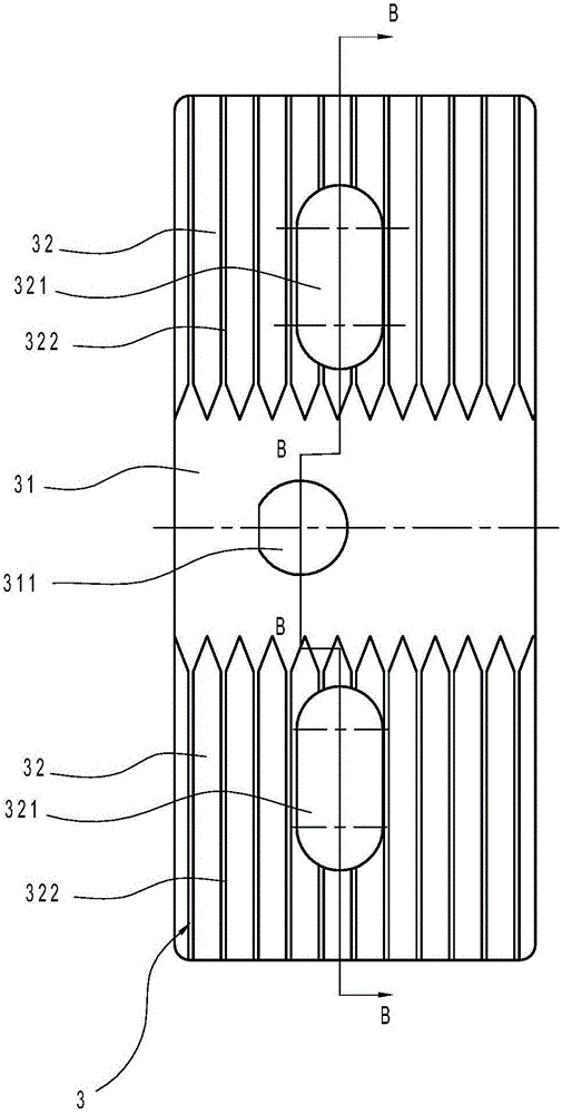
[0025] Such as Figures 1 to 13 As shown, the shaft knurling alignment device in this implementation includes positive knife arm 51, reverse knife arm 52, knife arm support slide plate 3, knurling wheel 7, bracket 9, positioning mandrel 4, spring leaf 1, fixed Bolt 2, double-ended screw rod 6, fastening bolt 11, back tight nut 12, roller shaft 8 and fastening screw 10.

[0026] Wherein, the positive knife arm 51 and the counter knife arm 52 are relatively arranged, the knife arm support slide plate 3 is used to connect the positive knife arm 51, the reverse knife arm 52, the bracket 9 is used to connect the knife arm support slide plate 3 and the processing machine tool, and the positive knife arm 51 One end of the knife arm and the counter knife arm 52 is respectively provided with a knurling wheel 7, and the other end of the positive knife ...


PUM


Abstract

The invention discloses a knurl aligning device for a shaft. The knurl aligning device for the shaft comprises a pair of positive tool arm and negative tool arm which are arranged opposite to each other and a tool arm supporting sliding plate used for connecting the positive tool arm and the negative tool arm, wherein knurl wheels are arranged at one ends of the positive tool arm and the negative tool arm respectively; and the other ends of the positive tool arm and the negative tool arm are arranged on the tool arm supporting sliding plate. The knurl aligning device for the shaft is characterized by also comprising a bracket used for connecting the tool arm supporting sliding plate and a processing machine, a positioning core shaft and spring leaves, wherein through holes are correspondingly formed in the tool arm supporting sliding plate and the bracket respectively; the positioning core shaft penetrates through the through holes of the supporting sliding plate and the bracket; the spring leaves are arranged on the two sides of the bracket respectively; one ends of the leaf springs are fixed to the bracket; the other ends of the leaf springs are abutted to the side part of the tool arm supporting sliding plate; and two spring leaves limit rotation of the tool arm supporting sliding plate with the positioning core shaft as the center. The invention provides the knurl aligning device for the shaft, which can realize self-centering and improve the processing efficiency and accuracy of a shaft spline.

Description

technical field [0001] The invention relates to a positioning alignment device, in particular to a shaft knurling alignment device. Background technique [0002] For a splined connection, one end of the shaft needs to be knurled, such as the drive shaft found in a vehicle fan clutch. For example, the Chinese invention patent with the existing publication number 204799979U discloses "A Kind of Knurled Knife", which includes a base, a knife arm, a locking device and a knurled knife, and is characterized in that two sides of the top of the base are hinged. Knife arm, the free end of the knife arm is hinged with a knurling knife, the middle part of the knife arm is provided with a guide hole, the guide rail arranged on the base passes through the guide hole, and the guide hole is also provided with two knife arms Fixed locking device. However, the knurling cutter needs to manually adjust the center height between the knurling cutter and the axis of the machining shaft during t...

Claims


Application Information

Patent Timeline
Patent Type & Authority Applications(China)
IPC IPC(8): B23P9/02
CPCB23P9/02
Inventor 刘良根徐耀斌钱世荣
Owner WARNER SHENGLONG NINGBO CO LTD
Why Eureka
Try Eureka