Automatic sealing ring sleeving device

A sealing ring and power device technology, applied in transportation and packaging, metal processing, metal processing equipment, etc., can solve the problems of low work efficiency, the sealing ring stuck in the annular groove, large manpower, etc., and achieve the effect of improving work efficiency

Active Publication Date: 2016-06-29
NINGBO BLUE WHALE AUTOMATION TECH CO LTD
View PDF4 Cites 21 Cited by
  • Summary
  • Abstract
  • Description
  • Claims
  • Application Information

AI Technical Summary

Problems solved by technology

Manual installation requires a lot of manpower and low work efficiency
In addition, due to the setting of the annular notch in this step, workers will easily get the sealing ring stuck in the annular notch during the installation process, resulting in even lower work efficiency

Method used


Image

  • Automatic sealing ring sleeving device
  • Automatic sealing ring sleeving device
  • Automatic sealing ring sleeving device

Examples


Embodiment Construction

[0021] The present invention will be further described in detail below in conjunction with the accompanying drawings and embodiments.

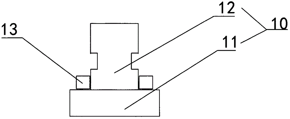
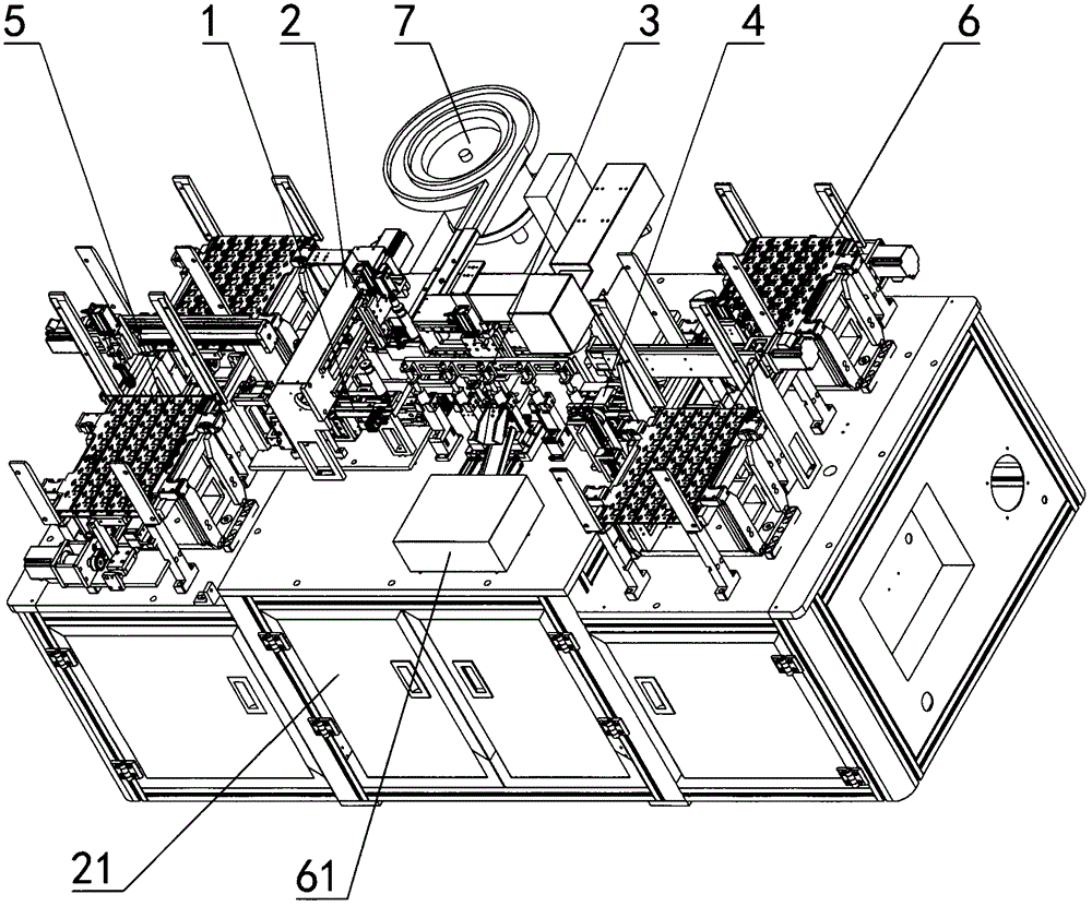
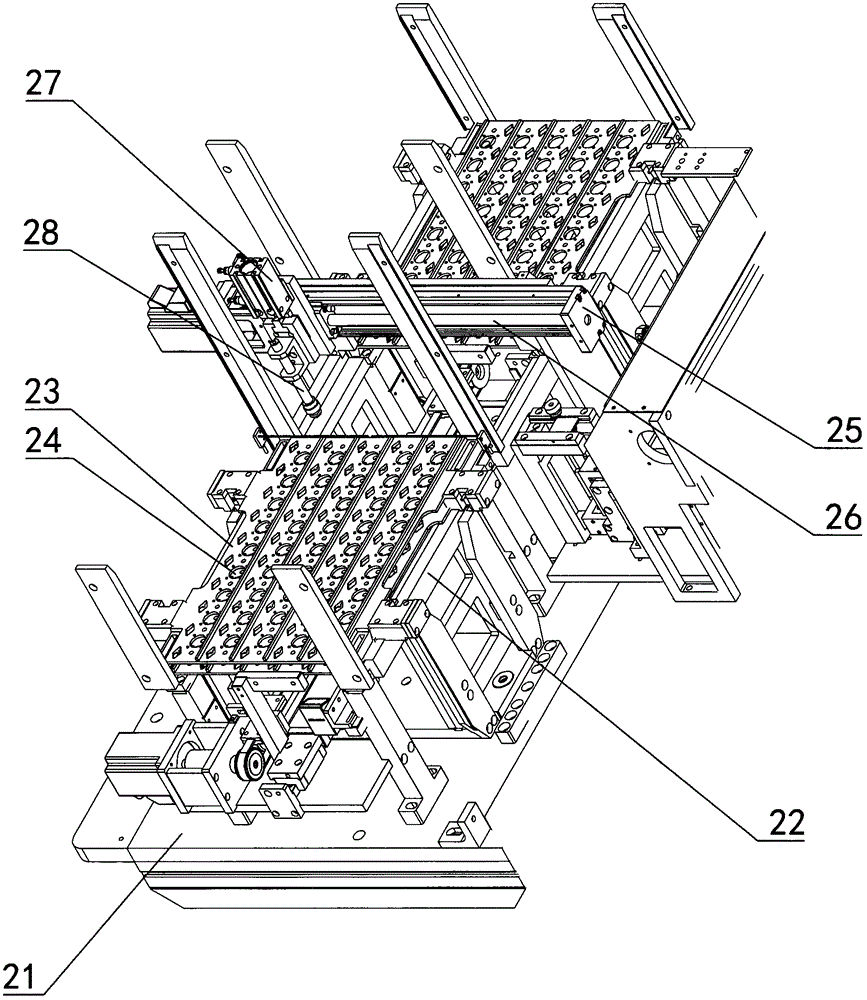
[0022] Such as Figure 1 to Figure 7 Shown: an automatic sealing ring device, including a power device that provides motion power, a turning mechanism 1, a sealing ring assembly mechanism 2, a detection mechanism 3, a laser marking mechanism 4, and a loading mechanism 5 and a discharging mechanism with the same structure Mechanism 6, the feeding mechanism 5 is connected to the head end of the turning mechanism 1, the sealing ring assembly mechanism 2 is connected with a vibrating plate 7 with a large number of sealing rings 13, the sealing ring assembly mechanism 2 is connected to the end of the turning mechanism 1, and the turning mechanism 1. The detection mechanism 3 is connected with the laser marking mechanism 4, and the laser marking mechanism 4 is connected with the discharging mechanism 6;

[0023] The heads 11 of the copper and alumi...


PUM


Abstract

The invention discloses an automatic sealing ring sleeving device. The automatic sealing ring sleeving device comprises a power device for providing motion power, a turnover mechanism, a sealing ring assembly mechanism, a detection mechanism, a laser marking mechanism, a feeding mechanism and a discharging mechanism, wherein the feeding mechanism and the discharging mechanism are of the same structure. The feeding mechanism is connected with the head end of the turnover mechanism. A vibration disc for containing a large number of sealing rings is connected to the sealing ring assembly mechanism. The sealing ring assembly mechanism is connected with the tail end of the turnover mechanism. The turnover mechanism is connected with the laser marking mechanism through the detection mechanism. The laser marking mechanism is connected with the discharging mechanism. The automatic sealing ring sleeving device is composed of the power device, the turnover mechanism, the sealing ring assembly mechanism, the detection mechanism, the laser marking mechanism, the feeding mechanism and the discharging mechanism, wherein the feeding mechanism and the discharging mechanism are of the same structure. Mechanization and automation are adopted for replacing manpower to mount the sealing rings on aluminum-copper pole pillars, and the work efficiency is greatly improved.

Description

technical field [0001] The invention relates to the field of automatic assembly, in particular to an automatic sealing ring device. Background technique [0002] A copper-aluminum pole is involved in the automotive lithium battery. Such as figure 1 As shown, it is a cross-sectional view of a copper-aluminum pole. The copper-aluminum pole includes a head and a rod. The outer surface of the rod of the copper-aluminum pole is provided with an annular notch. In order to meet the assembly requirements, it is now necessary to cover the sealing ring on the copper and aluminum poles, and the sealing ring is located under the annular notch. [0003] At present, the assembly between the copper-aluminum pole and the sealing ring is carried out manually. During the installation process, the worker needs to expand the sealing ring first, then insert it into the copper-aluminum pole, and finally dial the sealing ring to the appropriate position. Location. The way of manual installatio...

Claims


Application Information

Patent Timeline
Patent Type & Authority Applications(China)
IPC IPC(8): B23P19/00
CPCB23P19/00B23P2700/50
Inventor 童剑锋
Owner NINGBO BLUE WHALE AUTOMATION TECH CO LTD
Why Eureka
Try Eureka