
Automatic bolt righting machine

A bolt, automatic technology, applied in the field of automatic bolt straightening machine, can solve the problem of non-uniform direction of the screw

Active Publication Date: 2016-06-29
天津国科医疗科技发展有限公司
View PDF7 Cites 0 Cited by
  • Summary
  • Abstract
  • Description
  • Claims
  • Application Information

AI Technical Summary

Problems solved by technology

[0006] The purpose of the present invention is to solve the problem that the direction of the screw rods is not uniform when the bolts are fed into the machine, and to provide an automatic bolt straightening machine. The bolts with positive clearance are uniformly aligned and sent out from the discharge pipe, which is convenient for the next step

Method used

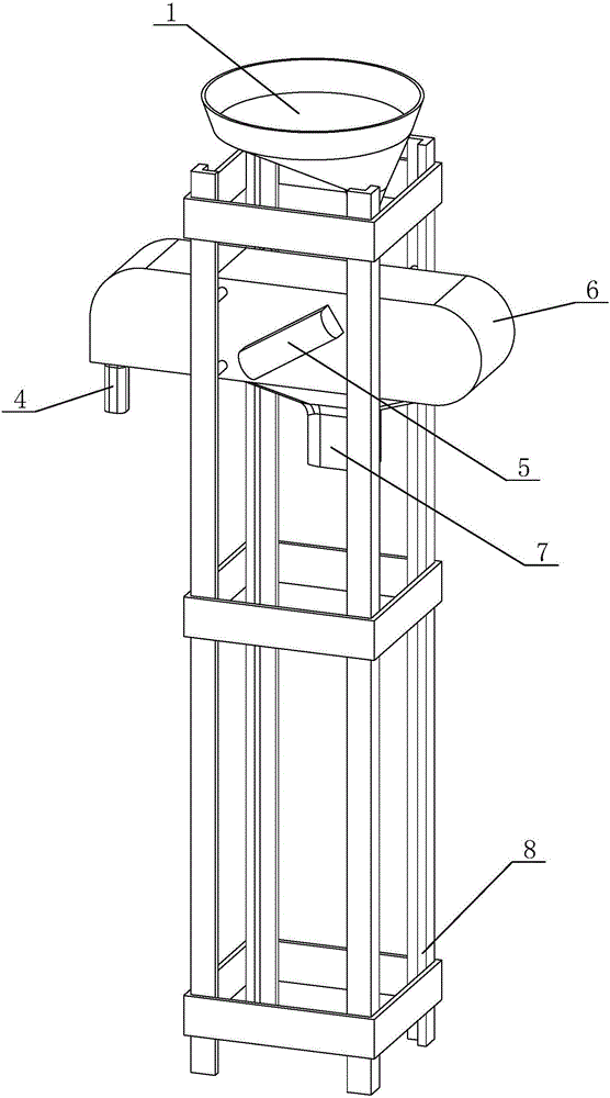
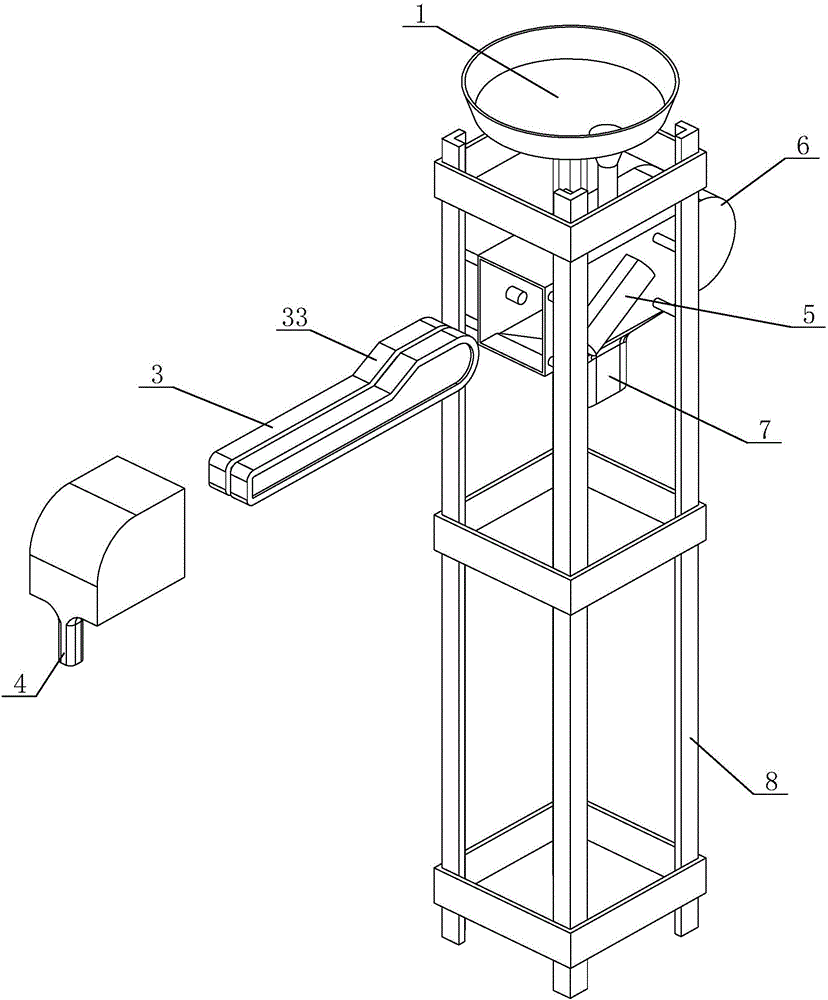
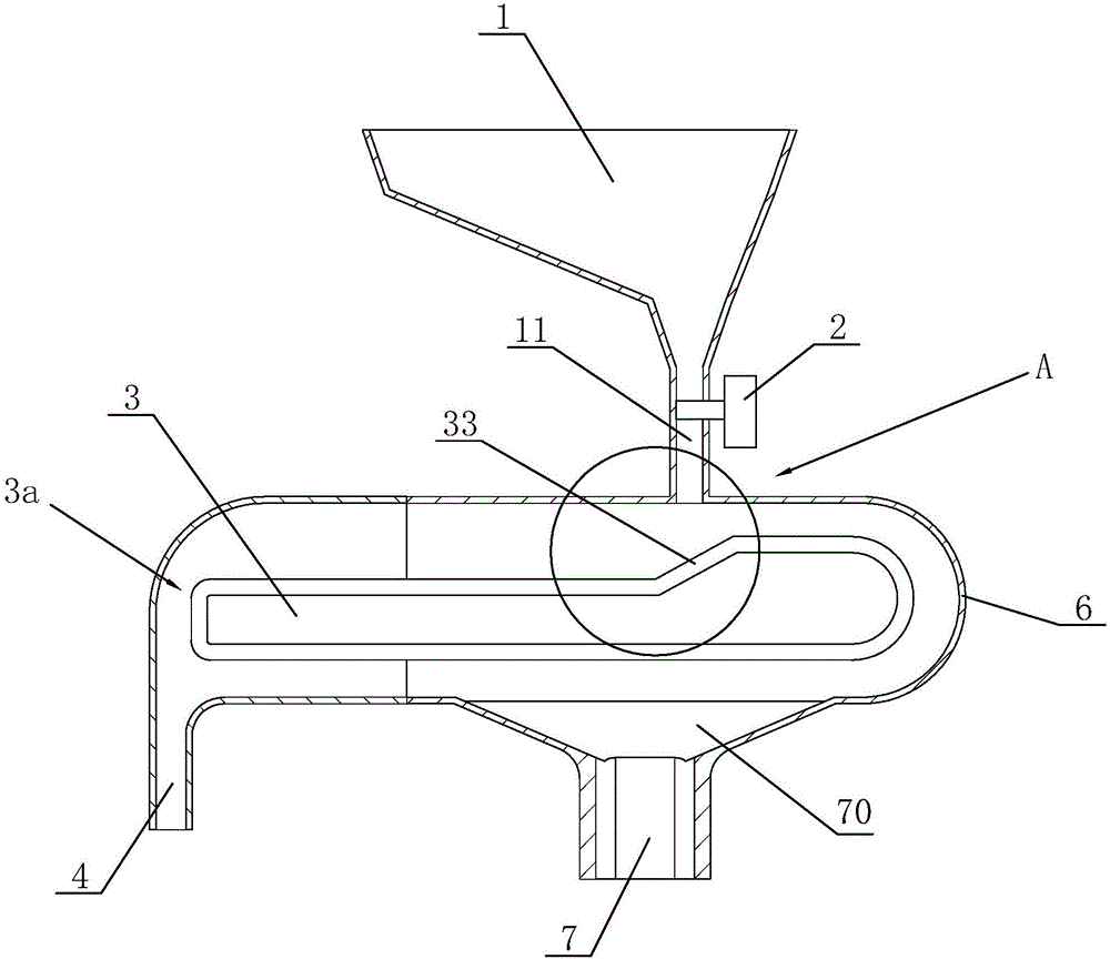

Image

  • Automatic bolt righting machine
  • Automatic bolt righting machine
  • Automatic bolt righting machine

Examples


Embodiment Construction

[0024] The present invention will be further described below in conjunction with the drawings.

[0025] The storage hopper 1 is responsible for adding bolts to the automatic bolt straightening machine through the conveying pipe 11 to maintain the normal operation of the machine;

[0026] The valve 2 is located on the side of the feed pipe 11, and is equipped with a timing open and close switch, which is responsible for timing the opening and closing of the feed pipe 11 to achieve the speed and time of managing the feeding. The opening and closing interval can be 1 second. It is ensured that the bolts of the feed pipe 11 falling on the conveyor belt 3 within one second within at least one second can effectively prevent the phenomenon of bolt stacking on the conveyor belt.

[0027] The conveyor belt 3 is the main working part of the entire automatic bolt straightening machine, which is responsible for receiving the bolts dropped from the feed pipe 11 and changing the direction of the b...


PUM


Abstract

The invention discloses an automatic bolt righting machine. The automatic bolt righting machine comprises a storage hopper, a valve, a conveyor belt, a discharge pipe and an outer shell. The storage hopper is arranged at the top of the outer shell and provided with a material passing pipeline used for feeding materials to the conveyor belt. The valve is installed on the side face of the material passing pipeline. The conveyor belt is arranged in the outer shell. A slope is arranged on the conveyor belt and located below the material passing pipeline. A righting gap only allowing screws of bolts to fall into is formed in the middle of the conveyor belt, and lateral gaps allowing bolts which fail to fall into the righting gap to fall off are formed in the two sides of the conveyor belt. The outer shell is provided with a vibrating mechanism used for vibrating the storage hopper and the conveyor belt. The bolts on the conveyor belt are screened in the vibrating mode through the vibrating mechanism, and the bolts entering the righting gap are righted uniformly and are sent out from the discharge pipe, so that further usage is facilitated.

Description

Technical field [0001] The invention relates to assembling equipment, which is an automatic bolt straightening machine. Background technique [0002] Most of the bolt machines in the current factory are manually filled with materials, which is extremely inefficient, too slow, and wastes manpower. [0003] There are also some machines on the market that use automatic feeding, which quickly feed bolts into the production machine through a conveyor belt, but they have certain disadvantages: [0004] 1. First of all, because there is no correcting mechanism, the direction of the bolts cannot be controlled during transportation. The bolts can stand up or down, which is difficult to apply to the next operation. [0005] 2. When the feeding time interval is large, the amount and time of feeding cannot be effectively controlled, and manual adjustment is still required, which causes great trouble to users. Summary of the invention [0006] The purpose of the present invention is to solve the p...

Claims


Application Information

Patent Timeline
IPC IPC(8): B65G47/18B65G65/44B65G47/28
CPCB65G47/18B65G47/28B65G65/44
Inventor 卢德林
Owner 天津国科医疗科技发展有限公司
Learn More