Automatic water level control switch of water supply system
A water level control and water supply system technology, applied in pump control, water supply devices, machines/engines, etc., can solve the problems of short life and high price
Active Publication Date: 2016-06-29
青岛瀚卓环保设备有限公司
View PDF6 Cites 9 Cited by
- Summary
- Abstract
- Description
- Claims
- Application Information
AI Technical Summary
Problems solved by technology
[0006] Aiming at the problems of high price and short service life of current rural water supply equipment, and the problem of manual switching between the village water supply system and the water supply system of individual wells, the present invention provides an automatic water level control switch for the water supply system. The purpose is to reduce the water pressure of the equipment, Reduce the cost of equipment; by se
Method used
View moreImage
Smart ImageViewing Examples

Examples
 PUM
 Abstract
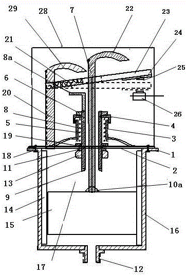
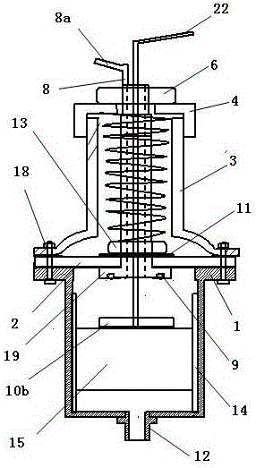
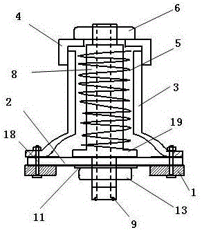
The invention discloses an automatic water level control switch of a water supply system, and belongs to the field of water supply. The water level control switch is arranged on a fixed plate, a hole is formed in the middle of the fixed plate, and a lifting part is fixed to the fixed plate. A floating part is arranged on the lower portion of the fixed plate. A spring sheet is arranged on the upper portion of the lifting part. The lifting part comprises a fixed barrel and a lifting pipe in the fixed barrel. The floating part comprises a sealed bucket fixed to the lower face of a bottom plate, a gravity floating body is arranged in the bucket, and a connecting rod in the vertical direction is fixed to the gravity floating body. When the water level rises, the connecting rod drives the lifting pipe to ascend, a top plate triggers the spring sheet, and the switch is switched off. When the water level drops, a pressing plate on the connecting rod presses the spring sheet, and the switch controls a water pump to run. By means of the switch, human resource cost can be reduced, personnel do not need to attend during water filling, the manufacturing cost of the water supply system can be reduced, and use and popularization are convenient. In addition, an original high-pressure water supply switch is changed into the automatic water level control switch, an external water source is preferably used for automatically supplying water into a water tower or water tank, and the expenses of families of farmers can be reduced.
Description
technical field [0001] The invention relates to a water supply control switch, in particular to an automatic water level control switch of a water supply system, which belongs to the field of water supply. Background technique [0002] At present, there are two main types of drinking water in rural areas: one is to drink water by yourself, manually control the water inlet and outlet of the water tower, and observe whether the water in the water tower is full through the overflow of the water tower, and then manually close the water tower until the overflow overflows , this method needs to send people to guard for a long time, which not only consumes manpower, but also wastes water resources; Figure 7 It is a schematic diagram of a representative rural water supply system at present. A water pump 33 is installed in the underground water well 34. An upper check valve 32 is installed on the inner water pipe 5 of the underground water well 34. A traditional water pressure contro...
Claims
Login to View More Application Information
Patent Timeline
 IPC IPC(8): F04B49/04E03B11/16
CPCF04B49/04
Inventor 焦昌堂焦慧颖
Owner 青岛瀚卓环保设备有限公司