
Durable low-cost automatic water level control switch

A water level control, low-cost technology, applied in the direction of pump control, water supply equipment, water supply main pipeline, etc., can solve the problems of high price and short life

Inactive Publication Date: 2016-08-10
郭菲
View PDF0 Cites 5 Cited by
  • Summary
  • Abstract
  • Description
  • Claims
  • Application Information

AI Technical Summary

Problems solved by technology

[0003] Aiming at the problems of high price and short service life of the current rural water supply equipment, and the problem of manual switching between the village water supply system and the water supply system of individual wells, the present invention provides a durable and low-cost automatic water level control switch, the purpose of which is to reduce the water pressure of the equipment , reduce the cost of equipment; by setting up water towers, the original high-pressure equipment is changed to low-pressure water supply, the original high-pressure water supply switch is changed to an automatic water level control switch, and external water sources are preferentially used to automatically supply water to the water tower or water tank, reducing the cost of water supply equipment , prolong the service life of water supply equipment, so that farmers can benefit

Method used


Image

  • Durable low-cost automatic water level control switch
  • Durable low-cost automatic water level control switch
  • Durable low-cost automatic water level control switch

Examples


Embodiment 1

[0020] Figure 8 It is a schematic diagram of the structure of the magnetic float valve. The use process of the magnetic float valve is as follows: it includes a valve body 101, a piston 102 with an iron 103 on the bottom surface, and a float 104; the upper end of the valve body 101 is provided with a connection port 105, and the side wall of the valve body 101 is provided with Pipe interface 106, the inner bottom surface of the valve body 101 is provided with a magnet 107; the piston 102 is placed in the valve body 101; 101 is installed below the water tower 31 through the connection port 105, and the floating ball 104 is placed in the water tower 31. When there is no water in the water tower 31, water enters the water tower 31 through the pipe interface 106 and the connection port 105. When the water level in the water tower 31 has not yet reached the set value and the pressure at the pipe interface 106 is greater than the pressure in the water tower 31, the water tower 31 ...

Embodiment 2

[0022] Figure 6 It is an automatic switching system between the external water source and the home water source. The external water source pipeline 42 and the household water source pipeline 35 are connected in the household water supply system. The external water source pipeline 42 is also provided with an external water source check valve 43. The household water source The pipeline 35 leads to the water well 34. On the household water source pipeline 35 connected to the water pump 33, a lower check valve 32 is arranged on the household water source pipeline 35 to supply water to the water tower 31 or the water tank by the water pump 33, and the water tower 31 or the water tank enters the water. The mouth is connected with the household water source pipeline 35 by a magnetic float valve one 39a or a magnetic float valve two 39b, and the household water source pipeline 35 is connected with a water end 44. When the external water source supplies water, the external water source...


PUM


Abstract

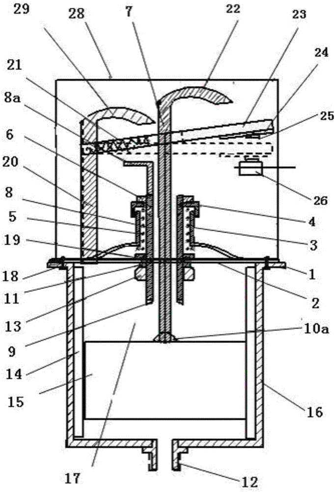
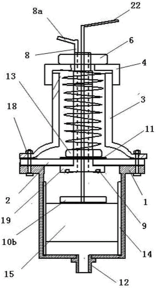
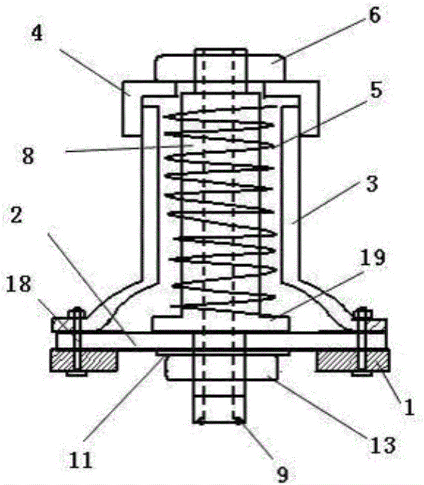
The invention discloses a durable and low-cost automatic water level control switch. The water level control switch is arranged on a fixed plate. A hole is arranged in the middle of the fixed plate. A lifting part is fixed on the fixed plate. The upper part of the upper part is provided with a spring leaf, the lifting part includes a fixed cylinder and a lifting tube inside the fixed cylinder, the floating part includes a sealed bucket fixed under the bottom plate, a gravity floating body is arranged in the bucket, and a vertical connection is fixed on the gravity floating Rod, when the water level rises, the connecting rod drives the lifting tube to rise and the top plate touches the spring piece, and the switch is disconnected; when the water level drops, the upper pressure plate of the connecting rod presses down the spring piece, and the switch controls the operation of the water pump. Using this switch can reduce the cost of human resources, no need Waiting for water supply can reduce the cost of the water supply system and facilitate popular use.

Description

technical field [0001] The invention relates to a water supply control switch, in particular to a durable and low-cost automatic water level control switch, which belongs to the field of water supply. Background technique [0002] At present, there are two main types of drinking water in rural areas: one is to drink water by yourself, manually control the water inlet and outlet of the water tower, and observe whether the water in the water tower is full through the overflow of the water tower, and then manually close the water tower until the overflow overflows , this method needs to send people to guard for a long time, which not only consumes manpower, but also wastes water resources; Figure 7 It is a schematic diagram of a representative rural water supply system at present. A water pump 33 is installed in the underground water well 34. An upper check valve 32 is installed on the inner water pipe 5 of the underground water well 34. A traditional water pressure control swi...

Claims


Application Information

Patent Timeline
Patent Type & Authority Applications(China)
IPC IPC(8): F04B49/025F16K31/22E03B7/09
CPCF04B49/025E03B7/09F16K31/22
Inventor 郭菲
Owner 郭菲
Learn More