Unlock instant, AI-driven research and patent intelligence for your innovation.
Six-way valve
What is Al technical title?
Al technical title is built by PatSnap Al team. It summarizes the technical point description of the patent document.
A technology of six-way valve and valve body, applied in the field of six-way valve, can solve the problems of complicated operation, complicated structure and high cost, and achieve the effects of good sealing effect, lower cost and easy installation.
Inactive Publication Date:
View PDF10 Cites 1 Cited by
Summary
Abstract
Description
Claims
Application Information
AI Technical Summary
This helps you quickly interpret patents by identifying the three key elements:
Problems solved by technology
Method used
Benefits of technology
Problems solved by technology
[0003] The purpose of the present invention is to overcome the deficiencies of the prior art, and provide a six-way valve, which mainly solves the problems of complex structure, cumbersome operation and high cost of the existing air-conditioning or cold storage defrosting valve group
Method used
Image
Click on the blue label to locate the original text in one second.
Reading with bidirectional positioning of images and text.
Examples
Embodiment 1
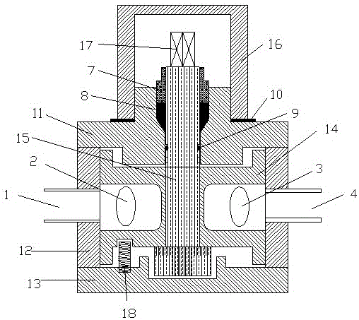
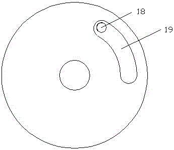
[0018] Example 1, see figure 1 , 2 According to the design requirements, the valve body 12 and the valve core 14 are processed, and pits or holes are set on the inner wall of the valve body 12; There are six channels 1, 2, 3, 4, 5, and 6 of A, B, C, D, E, and F; the cross section of the valve core 14 is Y-shaped, and the lower part of the valve core 14 is provided with a fan-shaped positioning ring groove 19; 12 The valve core 14 is installed inside, and the limit screw 18 is installed on the upper surface of the lower cover 13, and the upper part of the screw 18 is installed in the positioning ring groove 19; there is a hole in the middle of the valve core 14, and the valve stem 15 is installed, and the valve stem 15 is connected with the valve core 14 , and can be driven by the valve stem 15, the lower end of the valve stem 15 is installed in the blind hole in the lower cover 13; the upper surface of the upper cover 11 protrudes to form a boss, with a through hole in the mi...
Embodiment 2
[0021] Example 2, see Figure 7 , Same as the embodiment, the difference is that in order to make the valve rotate more flexibly, a bearing 20 is installed at the lower end of the valve stem 15, and the outer ring of the bearing 20 is installed in the blind hole of the lower cover 13.
Embodiment 3
[0022] Example 3, see Figure 8 , With embodiment 1, the difference is that a pit groove or hole is set on the inner wall of the valve core 14, and there is no pit groove or hole on the inner wall of the valve body 12; a check valve is installed on the E passage 5.
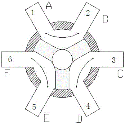
[0023] A kind of six-way valve of the present invention, when working, see Figure 5 , during normal operation, channel A communicates with channel B, channel C communicates with channel D, and channel E communicates with channel F. The refrigerant is discharged through the compressor 21, flows into the B channel through the A channel, and then flows into the condenser 22. The condensed refrigerant enters the liquid receiver 23, passes through the expansion valve 24 and flows into the aluminum row evaporator 25, and the evaporated refrigerant passes through The D channel flows into the C channel and then enters the compressor 21 .
[0024] E channel and F channel are closed because of being connected with check ...
PUM
Abstract
The invention discloses a six-way valve. The six-way valve comprises a valve body (12) which is provided with an upper cover (11) and a lower cover (13); the six-way valve is characterized in that the side wall of the valve body (12) is evenly provided with a channel A, a channel B, a channel C, a channel D, a channel E and a channel F, a valve element (14) is arranged in the valve body (12), a fan-shaped positioning ring groove (19) is formed in the lower portion of the valve element (14), and the upper portion of a limiting screw (18) on the upper surface of the lower cover (13) is installed in the positioning ring groove (19); a hole is formed in the middle of the valve element (14), a valve rod (15) is installed in the hole, and the lower end of the valve rod (15) is installed in a blind hole in the lower cover (13); the upper portion of the valve rod (15) is installed in a through hole of the upper cover (11), and a hard sealing piece (8) and a soft sealing piece (9) are installed between the through hole and the valve rod (15); and a sealing cover (16) is installed on the upper cover (11) and tightly presses a sealing gasket (10). The problem of defrosting of an air-conditioner refrigeration house can be solved through one valve, the valve set structure is abandoned, the structure is simpler, installation is easier, and the cost is substantially reduced.
Description
Technical field: [0001] The invention relates to the technical field of a fluid flow direction switching valve, in particular to a six-way valve which can switch the fluid direction of six channels, and is mainly used for air conditioner defrosting and fluid flow direction switching. technical background: [0002] At present, defrosting in air conditioners or cold storage often requires a valve group, the pipeline connection is cumbersome, the structure is complicated, the installation is troublesome, the fluid resistance is large, the operation process between the valves is also cumbersome, and the cost is high. Invention content: [0003] The purpose of the present invention is to overcome the deficiencies of the prior art, and provide a six-way valve, which mainly solves the problems of complex structure, cumbersome operation and high cost of the existing air-conditioning or cold storage defrosting valve group. [0004] The technical solution of the present invention is...
Claims
Application Information
Patent Timeline
Application Date:The date an application was filed.
Publication Date:The date a patent or application was officially published.
First Publication Date:The earliest publication date of a patent with the same application number.
Issue Date:Publication date of the patent grant document.
PCT Entry Date:The Entry date of PCT National Phase.
Estimated Expiry Date:The statutory expiry date of a patent right according to the Patent Law, and it is the longest term of protection that the patent right can achieve without the termination of the patent right due to other reasons(Term extension factor has been taken into account ).
Invalid Date:Actual expiry date is based on effective date or publication date of legal transaction data of invalid patent.

