Liquid heat exchange type air source heat pump

An air source heat pump and heat exchange technology, which is applied in the field of liquid heat exchange air source heat pump to achieve the effects of improving heat exchange efficiency, low structural cost and high degree of popularization

Active Publication Date: 2017-09-05
李澎
View PDF4 Cites 2 Cited by
  • Summary
  • Abstract
  • Description
  • Claims
  • Application Information

AI Technical Summary

Problems solved by technology

However, new options are still needed to better improve the performance of air source heat pumps in product design and engineering implementation

Method used


Image

  • Liquid heat exchange type air source heat pump
  • Liquid heat exchange type air source heat pump
  • Liquid heat exchange type air source heat pump

Examples


Embodiment 1

[0046] The following is a description of Embodiment 1.

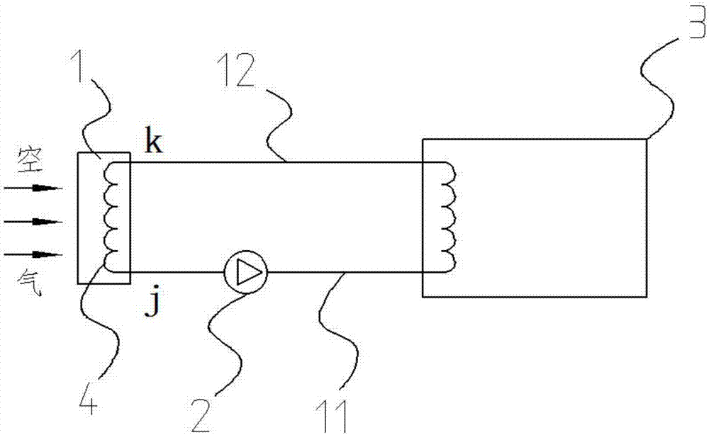
[0047] Such as figure 1 As shown, a liquid heat exchange type air source heat pump is characterized by comprising an air-liquid heat exchanger 1, a heat source liquid inlet pipeline 11, a heat source liquid return pipeline 12, a circulating pump 2, a liquid heat source heat pump 3, and a heat exchange tube Road 4, the air-liquid heat exchanger 1 is provided with a set of heat exchange pipelines 4, and the liquid outflow end j of the heat exchange pipeline 4 in the air-liquid heat exchanger 1 communicates through the heat source liquid inlet pipeline 11 To the inlet end j of the circulation pump 2, the outlet end of the circulation pump 2 is connected to the liquid inflow end of the heat exchange pipeline provided in the liquid heat source heat pump 3 through a pipeline, and the liquid of the heat exchange pipeline in the liquid heat source heat pump 3 flows out The end is connected to the liquid inflow end k of the heat...

Embodiment 2

[0049] The following is a description of Embodiment 2.

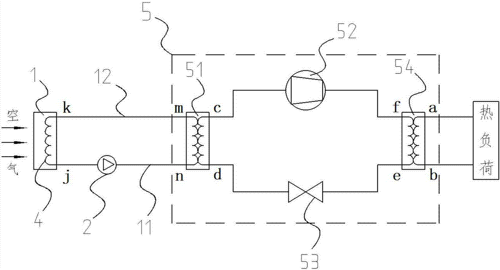
[0050] In Embodiment 2, the same symbols are assigned to the same structures as in the above-mentioned embodiments, and the same descriptions are omitted. Embodiment 2 is an implementation case of using compression heat pump 5 on the basis of embodiment 1. Such as figure 2 As shown, the compression heat pump 5 includes a first evaporator 51, a steam compressor 52, a throttle valve 53, and a first condenser 54. The port j of the air-liquid heat exchanger 1 passes through the heat source liquid inlet pipeline 11 is connected to the inlet port of the circulating pump 2, and the outlet port of the circulating pump 2 is connected to the port n on the first evaporator 51 in the compression heat pump 5 through pipelines. The first evaporator 51 is provided with two sets of heat exchange pipelines , one group communicates with port m and port n on the first evaporator 51, the other group communicates with port c and port d on...

Embodiment 3

[0052] The following is a description of Embodiment 3.

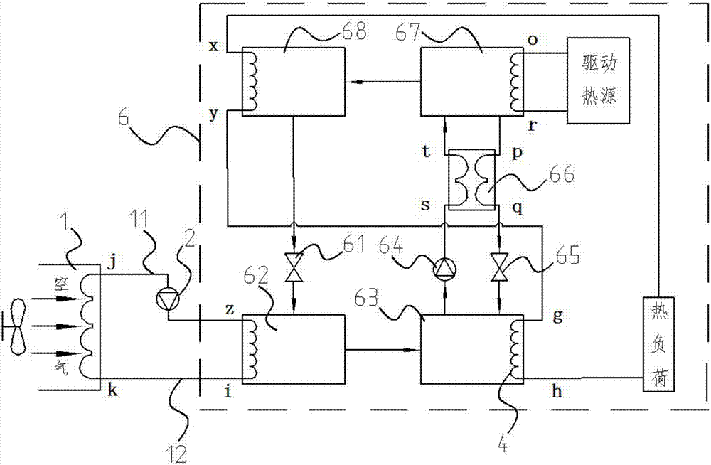
[0053] In Embodiment 3, the same symbols are assigned to the same structures as those in the above-mentioned embodiments, and the same descriptions are omitted. Embodiment 3 provides the embodiment that absorption heat pump 6 realizes embodiment 1, as image 3 As shown, the absorption heat pump 6 includes a solvent throttling valve 61, a second evaporator 62, an absorber 63, a solution pump 64, a solution throttling valve 65, a solution heat exchanger 66, a generator 67, a second condenser 68, the port j of the air-liquid heat exchanger 1 is connected to the inlet end of the circulation pump 2 through the heat source liquid inlet pipeline 11, and the outlet end of the circulation pump 2 is connected to the second evaporator in the absorption heat pump 6 through a pipeline Port z on 62, the second evaporator 62 is provided with a heat exchange pipeline to communicate with port z and port i, and port i of the second evapo...


PUM


Abstract

The invention discloses a liquid heat exchange type air source heat pump and relates to the technical field of air source heat pump systems. The liquid heat exchange type air source heat pump comprises a liquid heat source heat pump, a heat source liquid inlet pipeline, a heat source liquid return pipeline, an air liquid heat exchanger and a closed air channel. A heat exchange pipeline in the liquid heat source heat pump communicates with a heat exchange pipeline in the air liquid heat exchanger through the heat source liquid inlet pipeline and the heat source liquid return pipeline. A circulating pump is further arranged in the heat source liquid inlet pipeline or the heat source liquid return pipeline. The circulating pump drives heat exchange liquid to flow from the inside of the heat source liquid return pipeline to the liquid inflow end of the air liquid heat exchanger. An air pre-heat-exchange chamber is arranged at an air inlet of the closed air channel. One part of the heat source liquid return pipeline is arranged in the air pre-heat-exchange chamber. The air liquid heat exchanger is arranged on the non-air-pre-heat-exchange chamber part of the closed air channel. The problems of frosting and freezing of the heat pump and the cold island effect formed when the air source heat pump is arranged on a large scale are solved, large-area heat exchange can be achieved, the popularization degree is high, and practicability is high.

Description

technical field [0001] The invention relates to the technical field of air source heat pump systems, in particular to a liquid heat exchange type air source heat pump. Background technique [0002] After years of development, the air source heat pump has become one of the mainstream products in the energy-saving field, with its performance improving day by day and its cost constantly decreasing. The air generally contains water vapor, and it is generally believed that the most likely condition for water vapor condensation to occur is when the ambient temperature is between 5°C and 0°C and there is fog or rain and snow. If water vapor condenses on the surface of the air heat exchanger, as the air temperature further decreases, the condensed water on the surface of the heat exchanger will start to frost and freeze, which will reduce the heat exchange efficiency of the heat exchanger and affect the overall performance of the machine. efficiency. Some data show that due to the...

Claims


Application Information

Patent Timeline
Patent Type & Authority Applications(China)
IPC IPC(8): F25B30/06F25B30/02F25B30/04F25B47/02
CPCF25B30/02F25B30/04F25B30/06F25B47/022
Inventor 李澎王霞张忠玲
Owner 李澎
Why Eureka
Try Eureka