Apparatus and method for providing a visual indication of seal integrity

A technology for visual indication and integrity, used in fluid tightness testing, mechanical equipment, engine sealing, etc., to solve problems such as failure of mechanical parts seals that are not disclosed.

Inactive Publication Date: 2016-06-29
CATERPILLAR INC
View PDF1 Cites 4 Cited by
  • Summary
  • Abstract
  • Description
  • Claims
  • Application Information

AI Technical Summary

Problems solved by technology

While the methods disclosed by Kanakkanatt include the use of photochromic, chemochromic or piezochromic dyes to indicate specific changes in

Method used


Image

  • Apparatus and method for providing a visual indication of seal integrity
  • Apparatus and method for providing a visual indication of seal integrity
  • Apparatus and method for providing a visual indication of seal integrity

Examples


Embodiment Construction

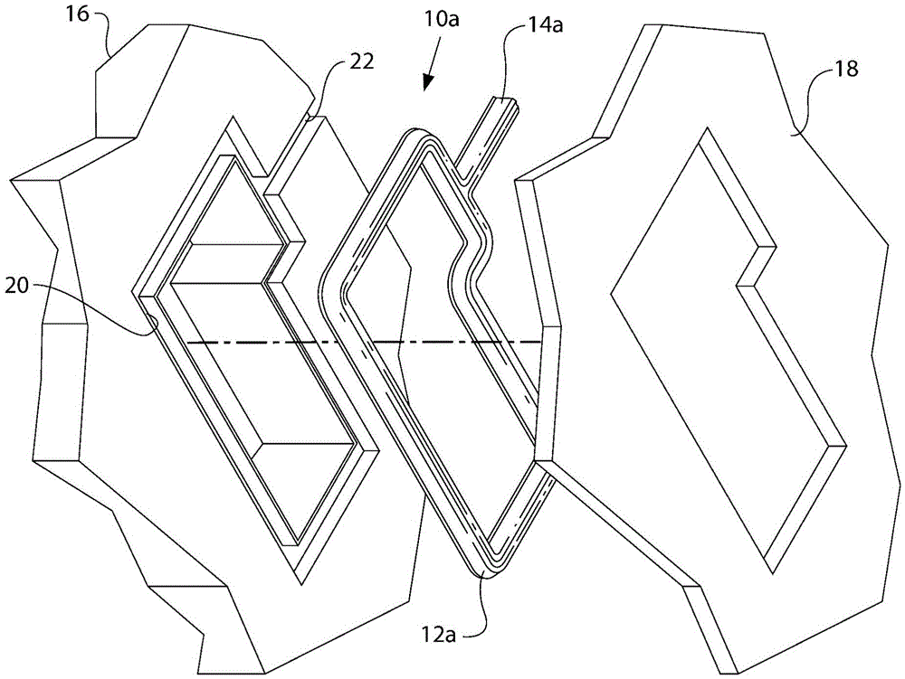
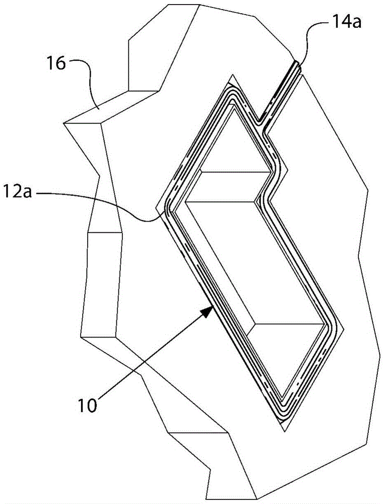
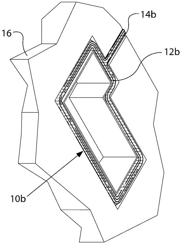
[0017] Reference now Figure 1-2B And 4A-4B, an embodiment of the sealing device 10a is shown, which includes a sealing member 12a and a tab member 14a configured to be used with the first structure 16 and the second structure 18. As in Figure 1-2B And 4A-4B, the sealing device 10a including the sealing member 12a and the tab member 14a can be used to describe the sealing device 10a and its parts under normal use conditions, and the sealing device 10b, the sealing member 12b and the tab member 14b are used Let's describe a sealing device that has undergone one or more changes in physical characteristics, as will be described here.

[0018] The sealing member 12a may be generally formed to have a length and a generally uniform cross-section along the length of the sealing member 12a, but a small size change of the cross-section may occur due to normal manufacturing variability. The sealing member 12a may generally include an outer periphery and an inner periphery. The sealing me...


PUM


Abstract

A seal device includes a seal member configured to seal a first component and a second component and a tab member formed on a seal member perimeter. The tab member is configured to extend substantially outward from the seal member perimeter to a respective component perimeter. The seal member and the tab member are formed from a mixture of a seal compound and a characteristic changing compound. The tab member is configured to provide a visual indication of seal integrity without separating the first component and the second component.

Description

Technical field [0001] The present invention relates to a sealing device, and more particularly to a sealing device that provides a visual indication of seal integrity or lack of seal integrity and a method of forming such a sealing device. Background technique [0002] Seals are used in many applications to prevent fluid leakage between two structures. The fluid seal is made of various materials and has a variety of design configurations. Such seals will begin to fail when exposed to high temperature or high pressure. [0003] Kanakkanatt’s US Patent No. 5501945 discloses the use of dyes in packaging materials that respond to specific stimuli and indicate exposure to stimuli by changes or shifts in the frequency of light absorbed by them. Although Kanakkanatt's disclosed methods include the use of photochromic, chemically variable or piezochromic dyes to indicate specific changes in the packaging material's environment, Kanakkanatt does not disclose the use of such dyes to detec...

Claims


Application Information

Patent Timeline
IPC IPC(8): G01M3/00
CPCF16J15/064G01M3/00
Inventor C·萨博塔J·克莱因
Owner CATERPILLAR INC
Why Eureka
Try Eureka