Device for in-situ detection of catalytic reaction intermediate and product and detection method
A catalytic reaction and in-situ detection technology, applied in measuring devices, material analysis through electromagnetic means, instruments, etc., can solve problems such as difficult detection of active intermediates, and achieve the effect of solving detection difficulties and promoting development
Inactive Publication Date: 2016-06-29
SHANGHAI JIAO TONG UNIV
View PDF5 Cites 16 Cited by
- Summary
- Abstract
- Description
- Claims
- Application Information
AI Technical Summary
Problems solved by technology
The device realizes the real-time online measurement and analysis of gas phase products in the catalytic reaction process, and is especial
Method used
View moreImage
Smart ImageViewing Examples
Examples
 PUM
| Property | Measurement | Unit |
|---|---|---|
| Hole diameter | aaaaa | aaaaa |
| Taper | aaaaa | aaaaa |
| Aperture | aaaaa | aaaaa |
Abstract
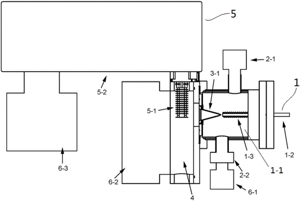
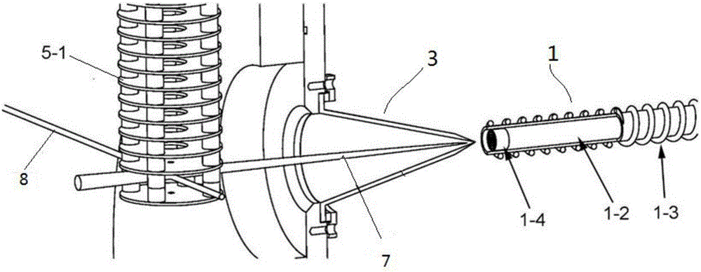
The invention relates to a device for in-situ detection of catalytic reaction intermediates and products, including a tubular catalytic reactor, a catalytic reaction chamber pressure control system, a sampling cone, an ionization chamber, a mass analysis system, and a vacuum system; The catalytic reactor includes a catalytic reaction chamber and a hollow reaction tube, both of which communicate with each other; the sampling cone is in the shape of a hollow cone, coaxially arranged with the hollow reaction tube, and the cone mouth is aligned with the outlet of the hollow reaction tube; the sampling cone and the ionization The cavity is connected, and the ion focusing electrostatic lens of the mass analysis system is set in the ionization cavity; the molecular beam enters the ion focusing electrostatic lens through the sampling cone, and completes ionization under the action of the ionization source, and enters the mass In-situ detection in the analysis system; the catalytic reaction chamber pressure control system controls the pressure in the catalytic reaction chamber; the vacuum system pumps the pressure in the catalytic reaction chamber, ionization chamber, and mass spectrometer of the mass analysis system respectively. vacuum.
Description
technical field [0001] The invention relates to a device and a detection method for in-situ detection of catalytic reaction intermediates and products, belonging to the technical field of in-situ detection of catalytic reaction intermediates and products. Background technique [0002] Catalytic technology is the main factor that promotes the production capacity and efficiency of the chemical industry. However, the development of catalytic technology has long relied on phenomenon observation and experience accumulation. In order to develop catalytic technology more effectively, it is necessary to deepen the understanding of the mechanism of catalytic action. Experimental research on temperature-controlled catalysis is the main research method in the field of basic catalysis research. It can provide species concentration and reaction process information related to temperature and residence time, and is an indispensable experimental basis for understanding the mechanism of cata...
Claims
Login to View More Application Information
Patent Timeline
 IPC IPC(8): G01N27/64
CPCG01N27/64
Inventor 周忠岳齐飞李玉阳
Owner SHANGHAI JIAO TONG UNIV
Features
- R&D
- Intellectual Property
- Life Sciences
- Materials
- Tech Scout
- Unparalleled Data Quality
- Higher Quality Content
- 60% Fewer Hallucinations
Learn More Browse by: Latest US Patents, China's latest patents, Technical Efficacy Thesaurus, Application Domain, Technology Topic, Popular Technical Reports.
© 2025 PatSnap. All rights reserved.Legal|Privacy policy|Modern Slavery Act Transparency Statement|Sitemap|About US| Contact US: help@patsnap.com


