
Antenna structure and installation method for wireless network coverage manhole cover

A wireless network and antenna structure technology, which is applied in the direction of antenna support/installation device, antenna, antenna parts, etc., can solve the problems of not realizing WiFi, scattered power supply at points, and unable to realize layout, etc., so as to achieve good guarantee and long service life Long, stable and reliable installation effect

Active Publication Date: 2018-07-17
康威通信技术股份有限公司
View PDF4 Cites 1 Cited by
  • Summary
  • Abstract
  • Description
  • Claims
  • Application Information

AI Technical Summary

Problems solved by technology

[0002] At present, WiFi wireless signals have covered public and private spaces such as homes, shops, office buildings, and office spaces. However, WiFi coverage has not been realized on the road, especially in the bustling commercial street. To achieve wireless coverage on the road, the required equipment installation carrier can only be Such as street light poles, advertising poles or building walls, however, these resources are affected by property ownership and location, and most of them cannot be deployed, and the points are scattered and power supply is difficult

Method used


Image

  • Antenna structure and installation method for wireless network coverage manhole cover
  • Antenna structure and installation method for wireless network coverage manhole cover
  • Antenna structure and installation method for wireless network coverage manhole cover

Examples


Embodiment Construction

[0032] The present invention will be further described below in conjunction with the drawings and specific embodiments of the description. The orientation terms such as "upper surface" and "lower surface" mentioned in the present invention are all relative positions adopted for the convenience of description, and cannot be understood as absolute positions. constitute a limitation of the invention.

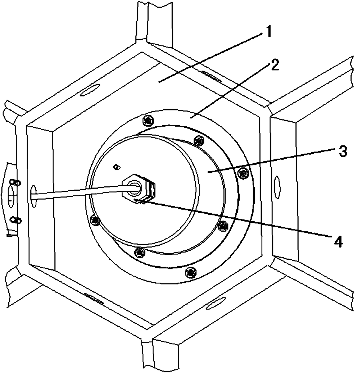
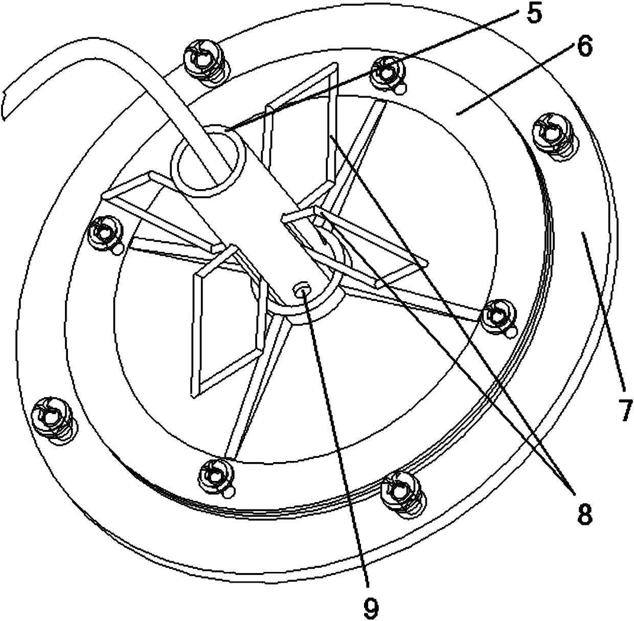
[0033] Such as figure 1 As shown, a wireless network covers the antenna structure of the manhole cover, including the antenna assembly, the antenna protection box 3, the waterproof joint 4, the bottom support ring 2 and the well cover 1, and the antenna assembly is fixed and installed on the back of the well cover 1 through the bottom support ring 2, The antenna protection box 3 is covered on one side of the antenna assembly to protect the antenna, and the waterproof connector is installed on the end face of the antenna protection box 3 .

[0034] The structure of the antenna asse...


PUM


Abstract

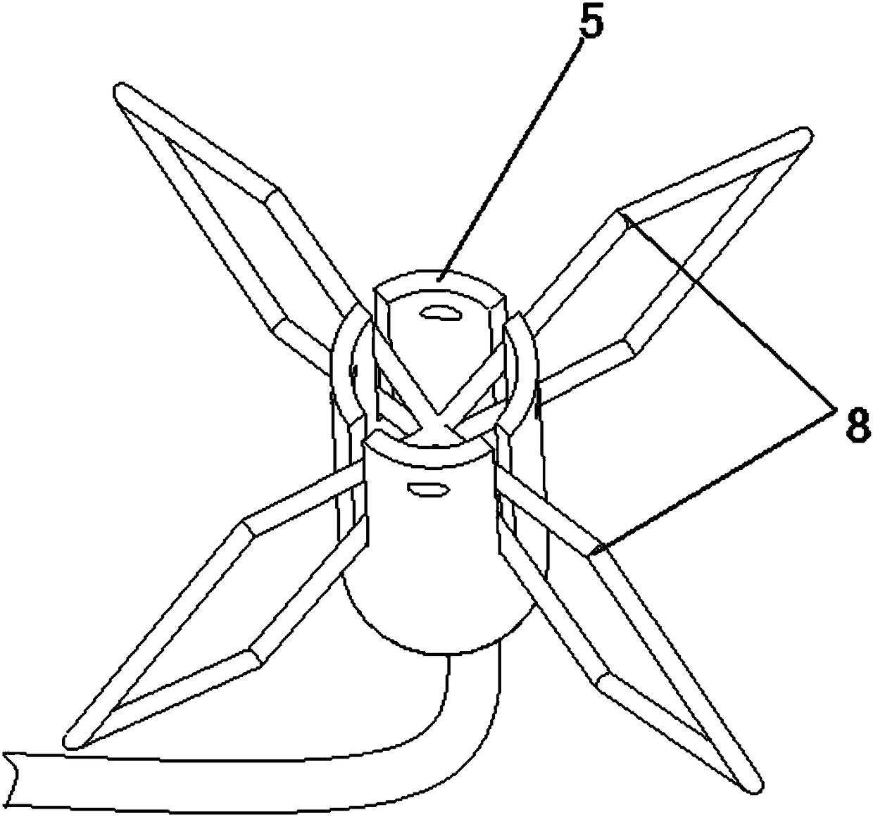
The invention discloses an antenna structure for a wireless network coverage manhole cover and an installation method of the antenna structure, and belongs to the technical field of electric power communication equipment safety. The antenna structure comprises antennas, an antenna installation pipe and an antenna base, wherein the antennas comprise a plurality of bracket structures in divergent distribution; the bracket structures of the antennas are clamped into clamping grooves of the antenna installation pipe; the clamping grooves of the antenna installation pipe and raised ribs in the antenna base are inserted together; and the antennas are fixedly arranged on the back surface of the manhole cover through the antenna base. During installation, the antennas are arranged in corresponding clamping grooves of the antenna installation pipe; the clamping grooves of the antenna installation pipe are fixed to the corresponding raised ribs in the antenna base; a waterproof joint is fixedly connected to an antenna protection box; the antenna protection box is fixedly arranged on the antenna base; and the formed assemblies are fixedly arranged on the back surface of the manhole cover. The antennas are stably and reliably fixed on the manhole cover; and a basis is provided for achieving complete coverage of wireless network communication.

Description

technical field [0001] The invention relates to the safety field of electric power communication equipment, in particular to an antenna structure and an installation method for a wireless network covering a manhole cover. Background technique [0002] At present, WiFi wireless signals have covered public and private spaces such as homes, shops, office buildings, and office spaces. However, WiFi coverage has not been realized on the road, especially in the bustling commercial street. To achieve wireless coverage on the road, the required equipment installation carrier can only be Such as street light poles, advertising poles or building walls, however, these resources are affected by property ownership and location, and most of them cannot be deployed, and the points are scattered and power supply is difficult. [0003] In addition to the functions of threading, access to equipment, personnel access, load bearing, and street beautification, pavement manhole covers (including ...

Claims


Application Information

Patent Timeline
Patent Type & Authority Patents(China)
IPC IPC(8): H01Q1/22H01Q1/42H01Q1/36
CPCH01Q1/1207H01Q1/22H01Q1/36H01Q1/42
Inventor 于冠军杨震威张明广
Owner 康威通信技术股份有限公司
Learn More