Falling weight deflectometer

A deflectometer and drop weight technology, which is applied in the fields of instruments, scientific instruments, and on-site foundation soil surveys, etc., can solve the problems of the cumulative duration reducing the overall survey efficiency, etc.

Active Publication Date: 2016-06-29
ДЮНАТЕСТ А/С
View PDF13 Cites 1 Cited by
  • Summary
  • Abstract
  • Description
  • Claims
  • Application Information

AI Technical Summary

Problems solved by technology

When several thousand consecutive measurements are to be made along the highway to be surveyed, the cumulative duration of the process reduces the efficiency of the overall survey

Method used


Image

  • Falling weight deflectometer
  • Falling weight deflectometer
  • Falling weight deflectometer

Examples


Embodiment Construction

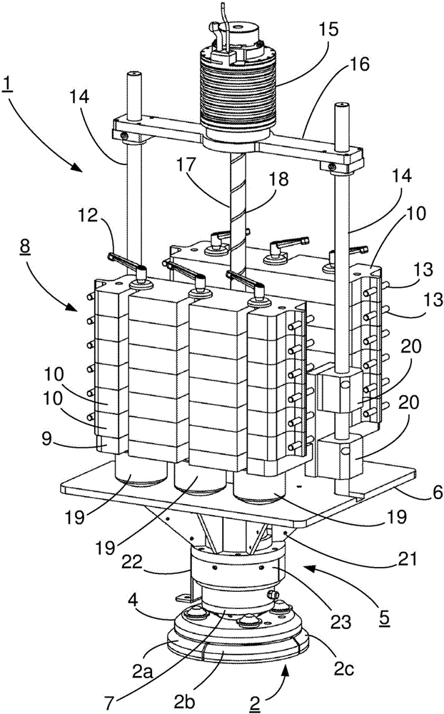
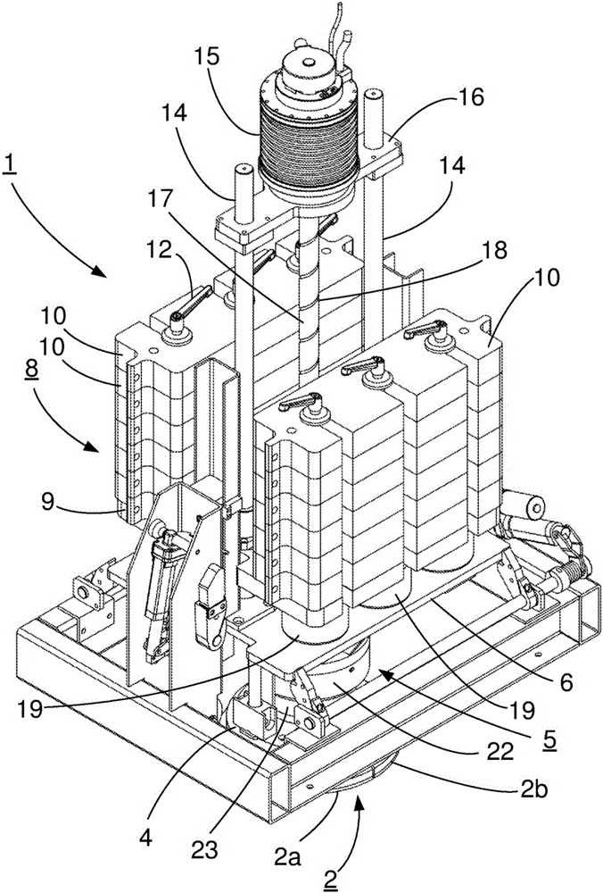
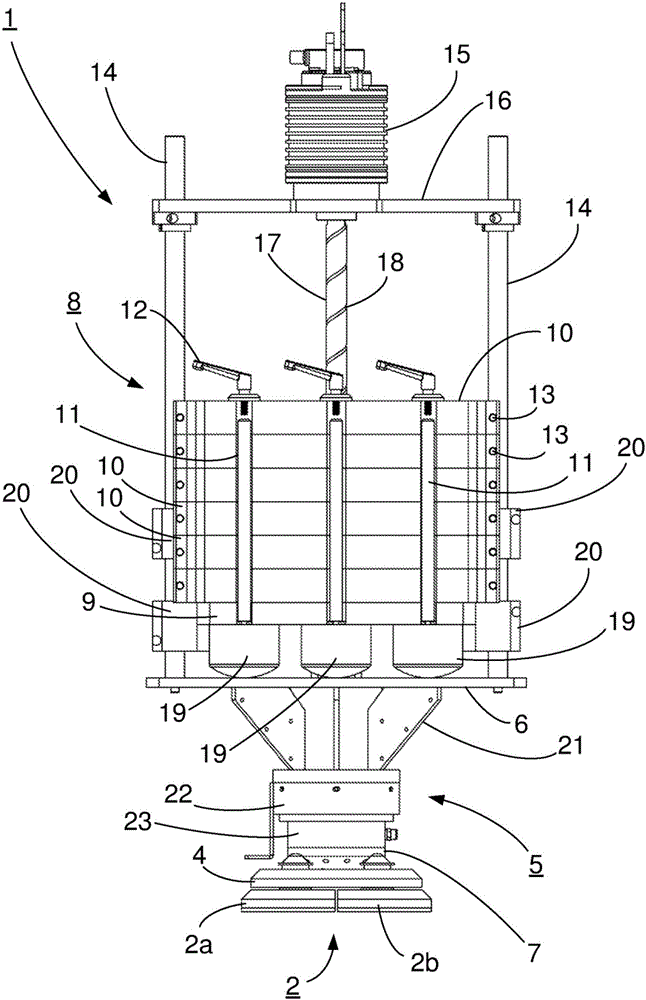
[0024] First refer to figure 1 , shows a perspective view of the core part of the falling weight deflectometer 1 according to the present invention. For the sake of mobility, in practice the falling weight deflection gauge 1 is mounted on a site known per se and at Figure 6a-Figure 6f on a suitable means of transport, such as a trailer or vehicle, as shown schematically in Reference is also made to the various descriptions in the above-mentioned article "Faldloddetshistorie", which is hereby incorporated by reference.

[0025] The falling weight deflectometer 1 comprises a falling weight 8 adapted to fall onto a load transfer plate 6 and impact the load transfer plate 6 from which the impact is transmitted via force transfer means to a test surface 30 (only in Figure 6a-Figure 6f ), such as for example a road surface of Portland cement concrete or asphalt concrete, the force transfer device comprises inter alia a support column 5 and a loading plate 2 adapted to engage wit...


PUM


Abstract

A falling weight deflectometer (1). The falling weight deflectometer comprises a load plate (2) adapted to engage a test surface, a force transmission means (5) adapted to transmit a force to the load plate (2), a buffer means (19), and a weight (8, 9, 10) adapted to impact said force transmission means (5) via said buffer means (19) so as to provide a force to be transmitted to said load plate (2) via said force transmission means, a guide means (14, 20) for guiding said weight (8, 9,10) towards said force transmission means, and a lifting means for lifting said weight to a predetermined height above said force transmission means. The lifting means comprises an electric (15) motor driving a threaded spindle in 17 engagement with the weight (8, 9, 10).

Description

technical field [0001] The invention relates to a falling weight deflectometer. Background technique [0002] A falling weight deflectometer (FWD) is a non-destructive testing device used by civil engineers to evaluate the physical properties of pavement structures. Data from FWD are primarily used to estimate load bearing capacity, especially for pavements including Portland cement concrete (PCC) or asphalt concrete (AC) surfaces. Applications include highways, airport pavements, and railway tracks. The drop-weight deflection gauge is usually integrated in a trailer that can be towed to the test location by another vehicle, but can also be integrated in the vehicle itself. [0003] The drop weight deflectometer is designed to impart a load pulse to the pavement surface, which mimics the load produced by a rolling wheel. This load is created by dropping a large weight onto a set of rubber bumpers. The resulting force is transmitted to the road surface via the circular lo...

Claims


Application Information

Patent Timeline
Patent Type & Authority Applications(China)
IPC IPC(8): G01N3/303E02D1/02G01N33/24
CPCG01N3/303G01N33/42
Inventor 雅各布·芬·马德森
Owner ДЮНАТЕСТ А/С
Why Eureka
Try Eureka