A gluing head with gluing nozzle rotation

A technology of gluing head and gluing nozzle, which is applied in the field of gluing head, can solve the problems such as the problem that the gluing nozzle cannot be rotated, and achieve the effect of reducing equipment cost, saving cost and expanding the scope of use.

Active Publication Date: 2018-06-12
DALIAN HUAGONG INNOVATION TECH
View PDF9 Cites 3 Cited by
  • Summary
  • Abstract
  • Description
  • Claims
  • Application Information

AI Technical Summary

Problems solved by technology

[0010] None of the above-mentioned patents can solve the problem of the rotation of the glue nozzle. At present, there is a lack of a glue head that can realize the rotation of the glue nozzle.

Method used


Image

  • A gluing head with gluing nozzle rotation
  • A gluing head with gluing nozzle rotation
  • A gluing head with gluing nozzle rotation

Examples


Embodiment 1

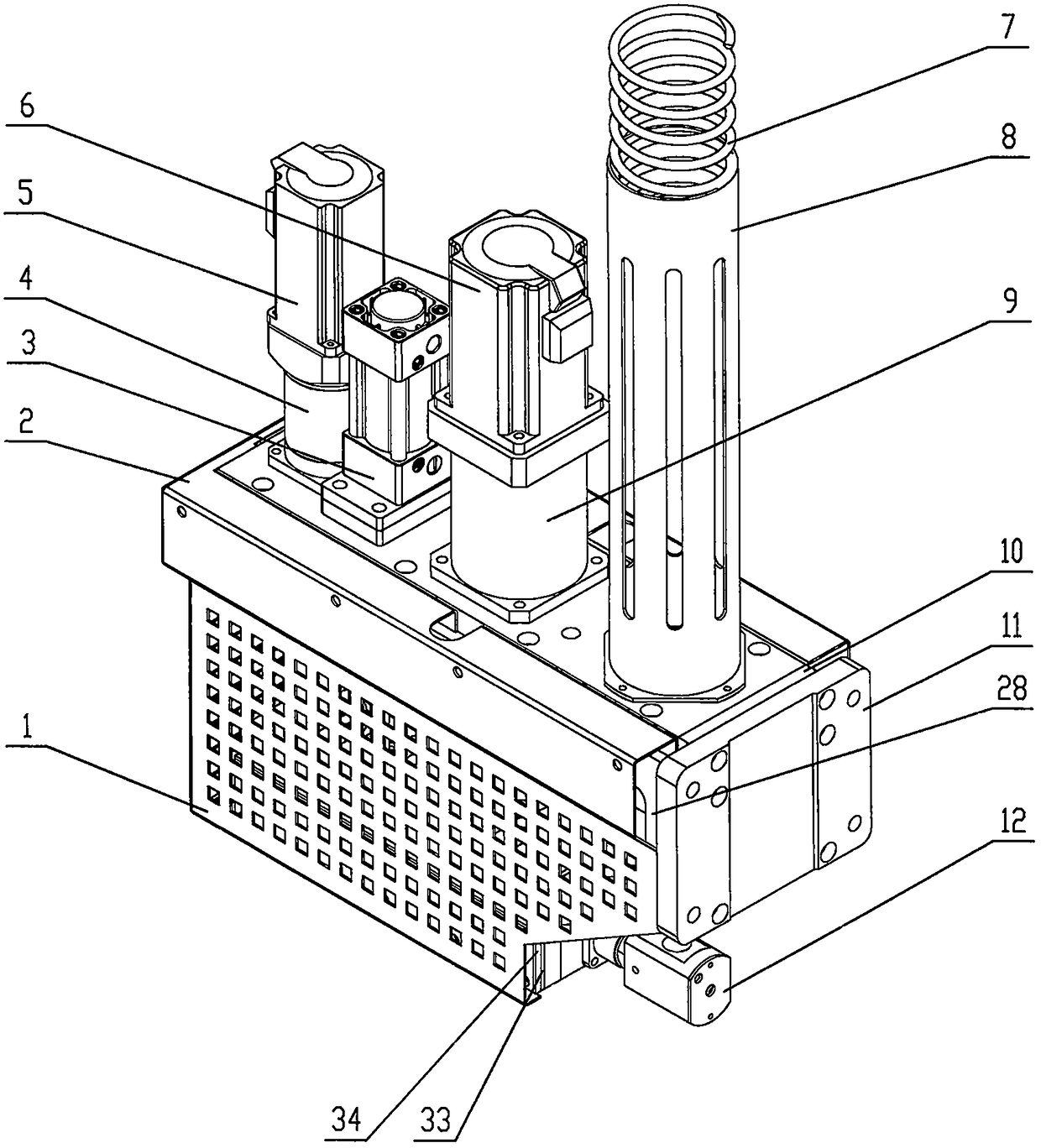
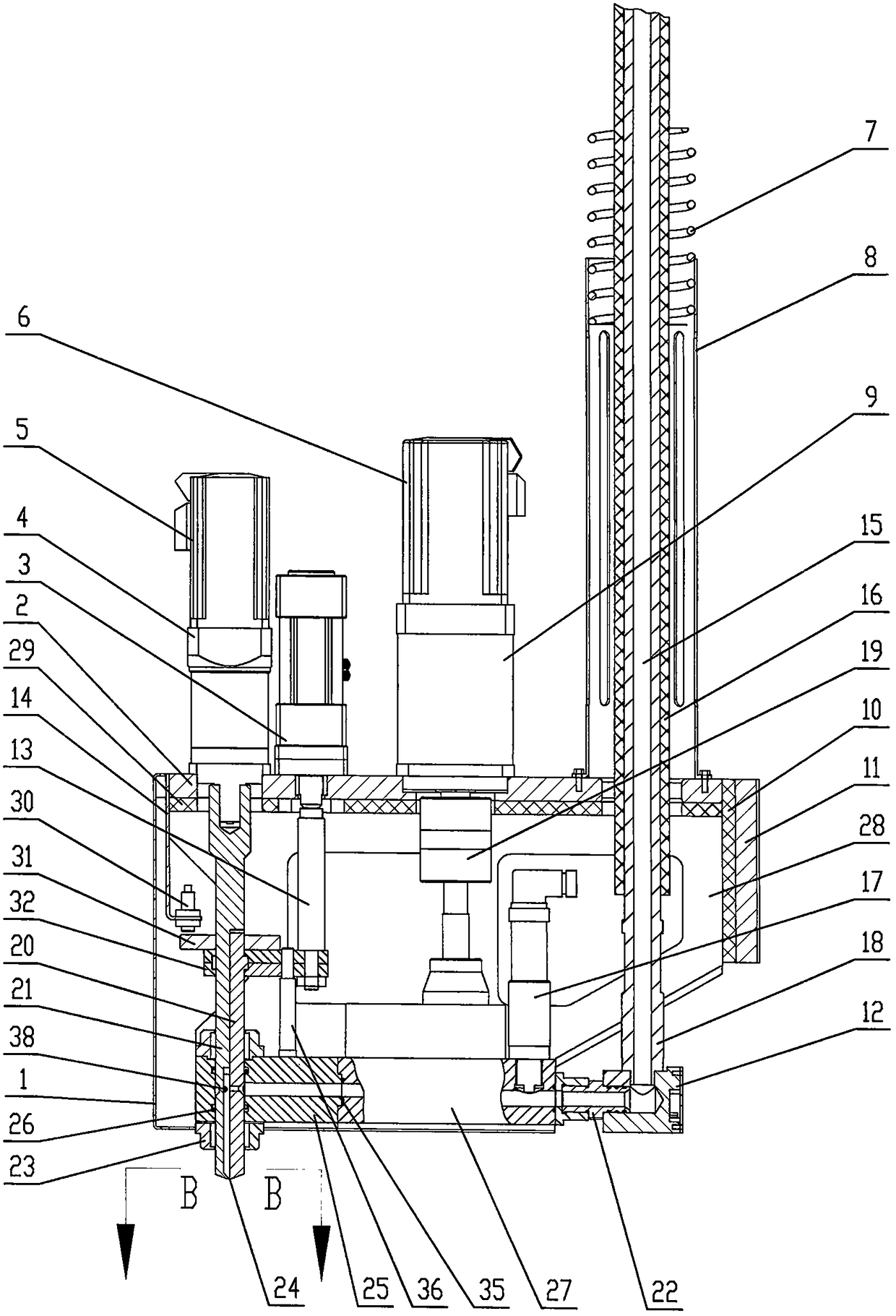
[0023] Embodiment 1: as Figure 1~3 Shown, further illustrate the present invention below in conjunction with accompanying drawing. A gluing head with a gluing nozzle rotating, used for gluing single-component glue, characterized in that it includes a gluing nozzle rotating mechanism, a gluing nozzle opening and closing mechanism, a glue supply metering device, a glue supply conveying device, the above mechanism and The device is fixed on the frame composed of the fixed plate 2, the heat shield B29, the heat shield A10, the fixed seat 11, and the bracket plate 28, the fixed seat 11 is connected with the gluing machine, and the shield 1 is installed on the above frame; the heat shield B29, heat shield A10 effectively protects heat transfer to reducer A4, reducer B9, and cylinder 3;

[0024] The nozzle rotation mechanism includes motor A5, reducer A4, nozzle A20, nozzle B21, transition body 25, guide seat 23, sealing ring A26, motor A5, reducer A4, nozzle B21 are fixedly connec...

Embodiment 2

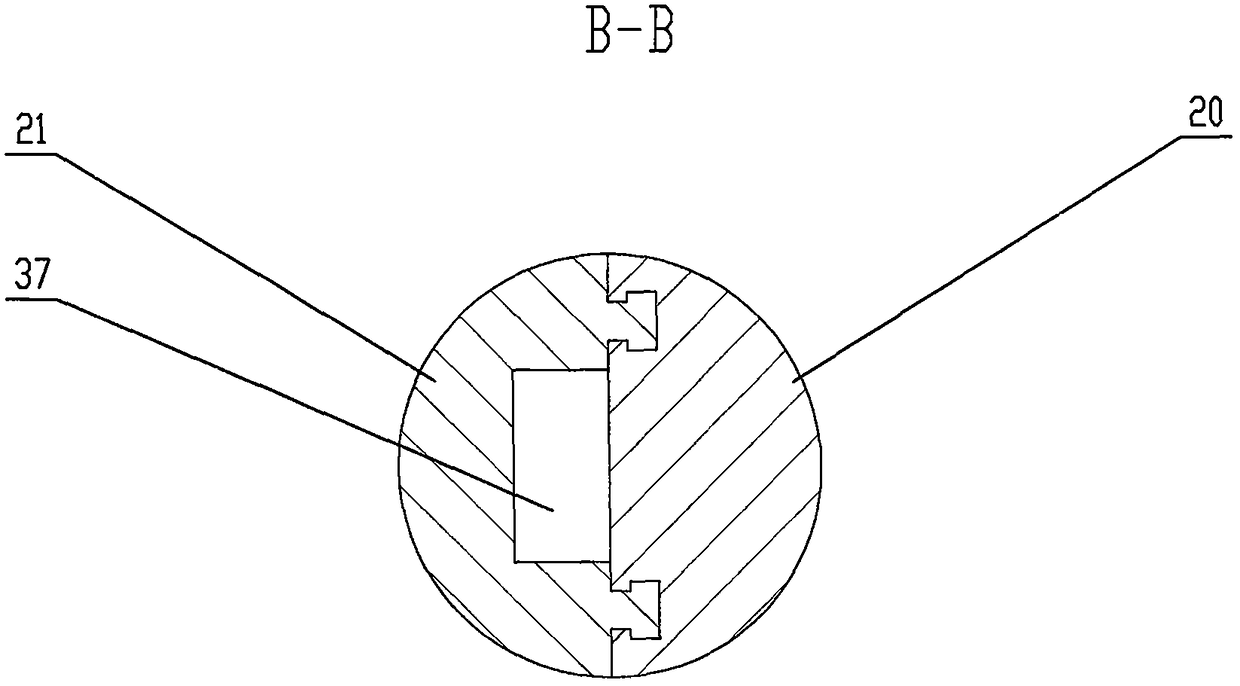
[0037] Embodiment 2 is different from Embodiment 1 in that the channel 37 cross-section of the glue nozzle 24 of the glue applicator is square or circular or elliptical or a combination of the above shapes, suitable for coating tracks that are flat or curved, and glue strips The cross-sectional shape is a square, an oval with a flat bottom, or a steamed bun-shaped workpiece.

[0038] working principle

[0039] A glue applicator with rotating glue nozzle includes a glue nozzle rotation mechanism, a glue nozzle opening and closing mechanism, a glue supply metering device, and a glue supply conveying device. The single-component glue enters the glue inlet channel of the glue hose assembly through the glue supply pump, The gear pump delivers to the glue inlet, when the lower end of the glue nozzle is opened, the one-component glue flows out; the rotation of the motor A and the reducer A drives the glue nozzle to rotate intermittently or continuously, which solves the problem of un...


PUM


Abstract

The invention discloses a gelatinizing head of gelatinizing equipment, and relates to a gelatinizing head with rotary gelatinizing nozzles for one-component glue. The gelatinizing head comprises a gelatinizing nozzle rotating mechanism, a gelatinizing nozzle opening and closing mechanism, a glue supply metering device and a glue supply conveying device which are fixed on a frame composed of a fixed plate, an insulation board B, an insulation board A, a fixed seat and a support plate; the gelatinizing nozzle rotating mechanism comprises a motor A, a speed reducer A, a gelatinizing nozzle A, a gelatinizing nozzle B, a transition body, a guide holder and a seal ring A, the motor A, the speed reducer A and the gelatinizing nozzle B are fixedly connected in sequence, the gelatinizing nozzle A and the gelatinizing nozzle B are combined through a trapezoidal slideway or a dovetail slideway, the gelatinizing nozzle A can move along the gelatinizing nozzle B in the axial direction, a movable plate is fixedly connected with a boss on the upper portion of the gelatinizing nozzle A, and the motor A and the speed reducer A rotatably drive the gelatinizing nozzles to rotate intermittently or continuously. Gelatinizing nozzle rotating is achieved, complex gelatinizing equipment is not needed, three-axis gantry gelatinizing equipment can also complete gelatinizing of workpieces, and the application range of the gelatinizing equipment is widened.

Description

technical field [0001] The invention relates to a gluing head of gluing equipment, which is used for the rotating gluing nozzle of one-component glue, especially for one-component hot-melt butyl glue, glass sealant, self-adhesive, Coating of type paper. Background technique [0002] There are many types of gluing heads at home and abroad. According to the structure of the valve body switch at the glue outlet, it can be divided into shaft-moving, cup-moving, and external valve-controlled gluing heads. [0003] "Multi-channel water cleaning two-component gluing head", patent number: ZL2012100552493, and "Multi-component polyurethane needle valve water cleaning gluing head", patent number: ZL2012100689458, which solved the two-component polyurethane gluing head must For the problem of using solvent to clean and not being able to use water to clean, a multi-channel water cleaning two-component polyurethane gluing head is provided. [0004] "Anti-drip glue applicator", the pate...

Claims


Application Information

Patent Timeline
Patent Type & Authority Patents(China)
IPC IPC(8): B05C5/02B05C11/10
CPCB05C5/02B05C11/1005
Inventor 韩旭韩毅军时丕林刘桂红
Owner DALIAN HUAGONG INNOVATION TECH
Why Eureka
Try Eureka