Threaded self-locking type automatic centering work fixture used for annular workpiece

A ring workpiece, automatic centering technology, applied in the field of clamping device, threaded self-locking fixture, can solve the problems of difficult disassembly, chuck wear, heavy weight, etc., to achieve convenient operation, long service life, simple and compact structure Effect

Inactive Publication Date: 2016-07-06
XIAN ZHONGZHI HUIZE PHOTOELECTRIC TECH
View PDF0 Cites 13 Cited by
  • Summary
  • Abstract
  • Description
  • Claims
  • Application Information

AI Technical Summary

Problems solved by technology

Under the guide part of the three jaws on the three-jaw chuck, there are threads that mesh with the plane threads on the back of the bevel gear. When the small bevel gear is turned with a wrench through the square hole, the bevel gear rotates, and the plane threads on the back simultaneously Drive the three jaws to approach or withdraw from the center to clamp workpieces with different diameters. However, if the three-jaw chuck is used for a long time, the chuck will wear out, and the three jaws will also appear bell-mouthed, making the three jaws deviate from the chuck. In addition, the three-jaw chuck still has the disadvantages of large volume, heavy weight, and difficult disassembly.

Method used


Image

  • Threaded self-locking type automatic centering work fixture used for annular workpiece

Examples


Embodiment Construction

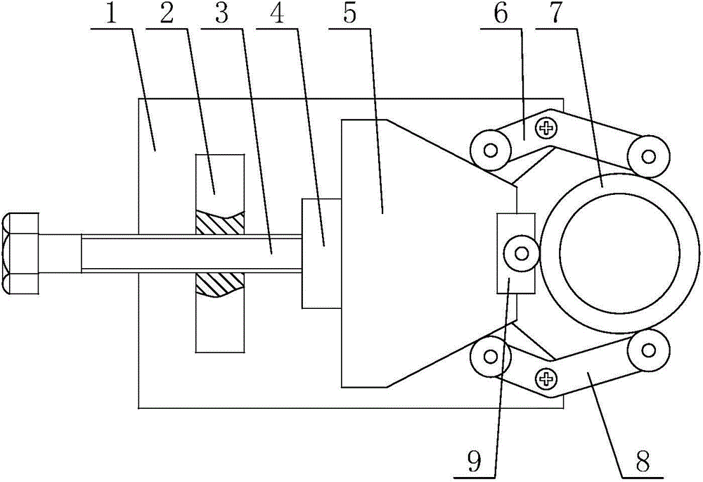
[0019] like figure 1 A threaded self-locking automatic centering tooling fixture for an annular workpiece as shown, includes a base plate 1 with a V-shaped groove at one end, and a bending arm 6 and a folding arm 6 that cooperate with each other to clamp the annular workpiece 7 from the outside. Bending arm 2 8, the inclined-plane pushing head 5 used to tighten the annular workpiece 7 in cooperation with the bending arm 1 6 and the bending arm 2 8, the drive screw for driving the inclined-plane pushing head 5 to move back and forth 3 and the screw seat 2 that cooperates with the driving screw 3 to form a thread transmission pair; the upper side of one end of the bottom plate 1 is rotatably installed with the bending arm one 6 and the bending arm two 8 that are symmetrical to each other, and the bottom plate 1. The screw seat 2 is fixedly installed on the upper side of the other end, and the drive screw 3 is installed on the screw seat 2 through a threaded hole. The rear end i...


PUM


Abstract

The invention discloses a threaded self-locking type automatic centering work fixture used for an annular workpiece. The automatic centering work fixture comprises a base plate, a folded bent arm I, a folded bent arm II, a bevel pushing head which matches the folded bent arm I and the folded bent arm II to push the annular workpiece tightly, a driving screw rod used for driving the bevel pushing head to move forward and backward and a screw rod seat which matches the driving screw rod to form a threaded transmission pair. The upper side of one end of the base plate is rotatably provided with the folded bent arm I and the folded bent arm II which are arranged symmetrically, while the upper side of the other end of the base plate is fixedly installed with the screw rod seat. The driving screw rod is installed on the screw rod seat through a threaded hole .The end of the driving screw rod is rotationally connected with the rear end of the bevel pushing head by a connection seat and the fore end of the bevel pushing head is fixedly installed with a pushing block. The fixture provided by the invention has the characteristics of being reasonable in design, simple in structure, capable of excircle centering clamping, high in force increasing ratio, good in self-locking property, convenient to operate and long in service life.

Description

technical field [0001] The invention belongs to the technical field of mechanical processing and relates to a clamping device, in particular to a threaded self-locking clamp which is used for clamping an annular workpiece and has the function of centering the outer circle. Background technique [0002] At present, in the machining process of shaft workpieces, the most commonly used clamping tool is a three-jaw chuck because the outer contour of the shaft workpiece has a certain radian. The three-jaw chuck is composed of a chuck body, movable jaws and jaw driving mechanism. Under the guide part of the three claws on the three-jaw chuck, there are threads that mesh with the plane threads on the back of the bevel gear. When the small bevel gear is turned with a wrench through the square hole, the bevel gear rotates, and the plane threads on the back simultaneously Drive the three jaws to approach or withdraw from the center to clamp workpieces with different diameters. However...

Claims


Application Information

Patent Timeline
Patent Type & Authority Applications(China)
IPC IPC(8): B23Q3/00B25B11/00
Inventor 侯鹏
Owner XIAN ZHONGZHI HUIZE PHOTOELECTRIC TECH
Why Eureka
Try Eureka