Disc cam driving type cylindrical workpiece centering and clamping fixture

A technology of cylindrical workpieces and disc cams, applied in the direction of manufacturing tools, metal processing machinery parts, clamping, etc., can solve the problems of difficult disassembly, chuck wear, heavy weight, etc., and achieve simple and compact structure, long service life, and automation high degree of effect

Inactive Publication Date: 2016-07-06
XIAN ZHONGZHI HUIZE PHOTOELECTRIC TECH
View PDF0 Cites 27 Cited by
  • Summary
  • Abstract
  • Description
  • Claims
  • Application Information

AI Technical Summary

Problems solved by technology

Under the guide part of the three jaws on the three-jaw chuck, there are threads that mesh with the plane threads on the back of the bevel gear. When the small bevel gear is turned with a wrench through the square hole, the bevel gear rotates, and the plane threads on the back simultaneously Drive the three jaws to approach or withdraw from the center to clamp workpieces with different diameters. However, if the three-jaw chuck is used for a long time, the chuck will wear out, and the three jaws will also appear bell-mouthed, making the three jaws deviate from the chuck. In addition, the three-jaw chuck still has the disadvantages of large volume, heavy weight, and difficult disassembly.

Method used


Image

  • Disc cam driving type cylindrical workpiece centering and clamping fixture

Examples


Embodiment Construction

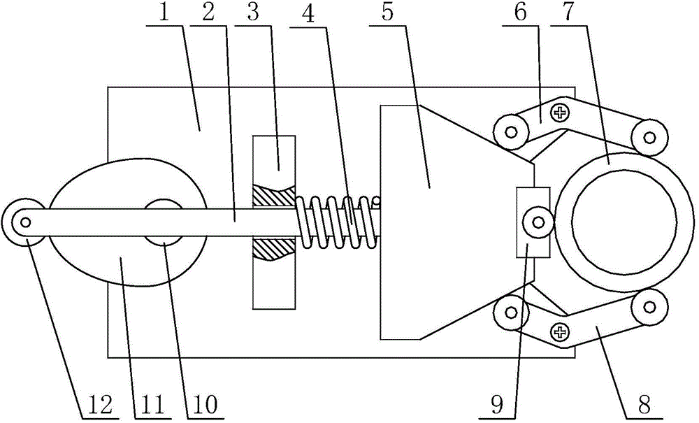
[0020] like figure 1 A disc-shaped cam-driven centering clamping fixture for a cylindrical workpiece as shown includes a bottom plate 1 with a V-shaped groove at one end, and an inclined-plane push head 5 for tightening a ring-shaped workpiece 7, and the inclined-plane push head 5 for pushing against the inclined-plane. The head 5 cooperates with the bending arm one 6 and the bending arm two 8 for clamping the cylindrical workpiece 7 from the outside, and cooperates with the drive spring 4 and the disc cam 11 for driving the inclined-plane push head 5 to move back and forth; The middle part of the bottom plate 1 is slidably installed with the slide bar 2 through the slide bar support 3, one end of the slide bar 2 is rotatably mounted with a roller 12, and the other end of the slide bar 2 is fixedly mounted with the front end with a top block 9. Inclined push head 5, a drive spring 4 is set on the slide rod 2 between the slope push head 5 and the slide bar support 3, and one en...


PUM


Abstract

The invention discloses a disc cam driving type cylindrical workpiece centering and clamping fixture which comprises a bottom plate, a bevel pushing head, a bent arm I, a bent arm II, a driving spring and a disc cam, wherein a sliding rod is mounted in the middle part of the bottom plate in a sliding manner through a sliding rod support; a roller is rotatably mounted at one end of the sliding rod; the bevel pushing head of which the front end has an ejecting block is fixedly mounted at the other end of the sliding rod; the driving spring is arranged on the sliding rod between the bevel pushing head and the sliding rod support in a sleeving manner; the disc cam tangential to the roller is rotatably mounted at one end of the bottom plate through a rotating shaft; and the bent arm I and the bent arm II which are mutually symmetrical are rotatably mounted on the upper side of the other end of the bottom plate. The disc cam driving type cylindrical workpiece centering and clamping fixture has the characteristics that the design is reasonable, the structure is simple, the excircle centering and clamping can be achieved, the disc cam is matched with the driving spring for utilization, the operation is convenient, the automation degree is high, and the service life is long.

Description

technical field [0001] The invention belongs to the technical field of mechanical processing and relates to a clamping device, in particular to a threaded self-locking clamp which is used for clamping an annular workpiece and has the function of centering the outer circle. Background technique [0002] At present, in the machining process of shaft workpieces, the most commonly used clamping tool is a three-jaw chuck because the outer contour of the shaft workpiece has a certain radian. The three-jaw chuck is composed of a chuck body, movable jaws and jaw driving mechanism. Under the guide part of the three claws on the three-jaw chuck, there are threads that mesh with the plane threads on the back of the bevel gear. When the small bevel gear is turned with a wrench through the square hole, the bevel gear rotates, and the plane threads on the back simultaneously Drive the three jaws to approach or withdraw from the center to clamp workpieces with different diameters. However...

Claims


Application Information

Patent Timeline
Patent Type & Authority Applications(China)
IPC IPC(8): B23Q3/00
Inventor 侯鹏
Owner XIAN ZHONGZHI HUIZE PHOTOELECTRIC TECH
Why Eureka
Try Eureka