Installation mechanism used for installing inner sleeve in tubular heat exchanger

A technology of tube heat exchanger and installation mechanism, which is applied in the direction of hand-held tools and manufacturing tools, which can solve the problems of damaged sealing ring, difficult knocking force, time-consuming and labor-intensive problems, so as to reduce the difficulty of installation and uniform force , the effect of reducing labor intensity

Inactive Publication Date: 2016-07-06
JIANGSU NEWAMSTAR PACKAGING MACHINERY
View PDF6 Cites 4 Cited by
  • Summary
  • Abstract
  • Description
  • Claims
  • Application Information

AI Technical Summary

Problems solved by technology

Due to the uneven force each time during the knocking process and the sealing ring of the outer casing has a certain degree of elasticity, the sealing ring is often damaged
In this installation method, it is difficult for the installer to control the magnitude of the knocking force, which is time-consuming and labor-intensive.

Method used


Image

  • Installation mechanism used for installing inner sleeve in tubular heat exchanger
  • Installation mechanism used for installing inner sleeve in tubular heat exchanger

Examples


Embodiment Construction

[0017] The technical solution of the present invention will be further described below in conjunction with the accompanying drawings.

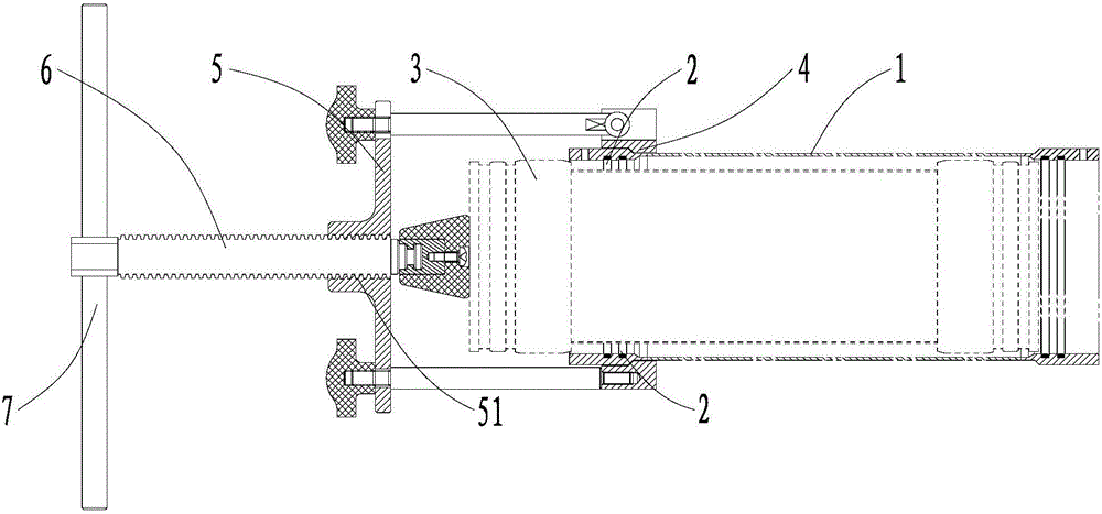
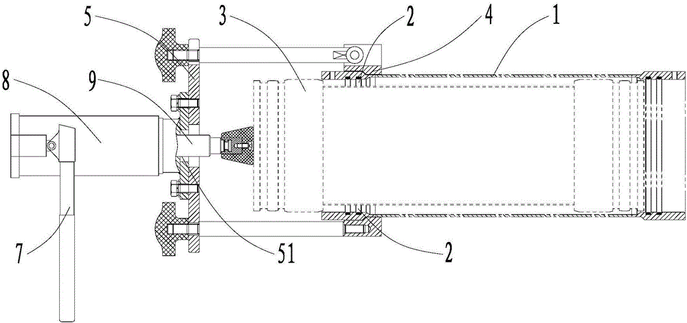
[0018] The above-mentioned installation mechanism for installing the inner casing in the tubular heat exchanger. The tubular heat exchanger is a floating tubular heat exchanger. The floating tubular heat exchanger includes an outer casing 1, a sealing ring 2 arranged inside the two ends of the outer casing 1, and a sealing ring 2 clamped in the outer casing 1. The inner casing 3. The installation mechanism is used to install the inner casing 3 into the sealing ring 2 smoothly. The inner sleeve 3 is a bundle of inner sleeves 3 composed of multiple tubes arranged in parallel.

[0019] The installation mechanism includes a first fixing part 4 arranged around one end of the outer casing 1 and a second fixing part 5 fixedly connected with the first fixing part 4 . The arrangement direction of the first fixing part 4 and the second fixing part 5 ...


PUM


Abstract

The invention discloses an installation mechanism used for installing an inner sleeve in a tubular heat exchanger. The tubular heat exchanger comprises an outer sleeve, sealing rings arranged on the inner sides of the two ends of the outer sleeve, and the inner sleeve. The installation mechanism is used for installing the inner sleeve into the sealing rings. The installation mechanism comprises a first fixing piece and a second fixing piece, wherein the first fixing piece is arranged outside one end of the outer sleeve in a sleeving mode, the second fixing piece is fixedly connected with the first fixing piece, and one end of the outer sleeve and the second fixing piece are distributed in a spaced mode. The arrangement direction of the first fixing piece and the second fixing piece is identical to the length extending direction of the outer sleeve. A through hole is formed in the second fixing piece. The installation mechanism further comprises a push rod and a handle, wherein the push rod is arranged in the through hole in a penetrating mode, the handle is arranged at the other end of the push rod, and the handle is used for driving the push rod to move in the length extending direction of the push rod during rotation. According to the installation mechanism, the push rod is driven by the rotation of the handle to move at a stable speed so that the inner sleeve can be stably pushed into the outer sleeve; and the acting force is uniform, the integrity of the sealing rings is guaranteed, the labor intensity of installation personnel is relieved, and the installation difficulty is lowered for the installation personnel.

Description

technical field [0001] The invention relates to an installation mechanism for installing an inner casing in a tubular heat exchanger. Background technique [0002] In the floating tube heat exchanger, the thermal expansion of the outer casing and the inner casing tube bundle is free, and the sealing is completely sealed by two sets of sealing rings in the joints on both sides of the outer casing casing, and the inner casing tube bundle can also be completely sealed. Pull out from the seal. [0003] In the floating tubular heat exchanger, before the inner sleeve tube bundle is loaded into the outer sleeve shell, two sealing rings must be installed at the joints on both sides of the outer sleeve shell. Therefore, the frictional resistance of the inner sleeve tube bundle increases when the inner sleeve tube bundle is packed into the outer sleeve shell, making it difficult to push the inner sleeve tube bundle into the outer sleeve shell. The traditional installation method is ...

Claims


Application Information

Patent Timeline
Patent Type & Authority Applications(China)
IPC IPC(8): B25B27/00
CPCB25B27/00
Inventor 茅嘉惠
Owner JIANGSU NEWAMSTAR PACKAGING MACHINERY
Why Eureka
Try Eureka