A High Precision Passive Resistor Generator Compensating for the Influence of Hardware Errors
What is AI technical title?
AI technical title is built by Patsnap AI team. It summarizes the technical point description of the patent document.
A passive resistor and generator technology, applied in the direction of resistors, adjustable resistors, other resistor networks, etc., can solve the problems of output accuracy dependence, resistance accuracy and low output accuracy, and achieve strong robustness and practicality sexual effect
Active Publication Date: 2018-03-27
SHENYANG YINXING TECH CO LTD
View PDF3 Cites 0 Cited by
Summary
Abstract
Description
Claims
Application Information
AI Technical Summary
This helps you quickly interpret patents by identifying the three key elements:
Problems solved by technology
Method used
Benefits of technology
Problems solved by technology
[0004] The main purpose of the present invention is to provide a high-precision passive resistance generator that compensates the influence of hardware errors, solve the problem that the output accuracy of existing passive resistance generators is completely dependent on resistance accuracy and the output accuracy is low, and improve the performance of passive resistors. Output accuracy
Method used
Image
Click on the blue label to locate the original text in one second.
Reading with bidirectional positioning of images and text.
Examples
Embodiment 1
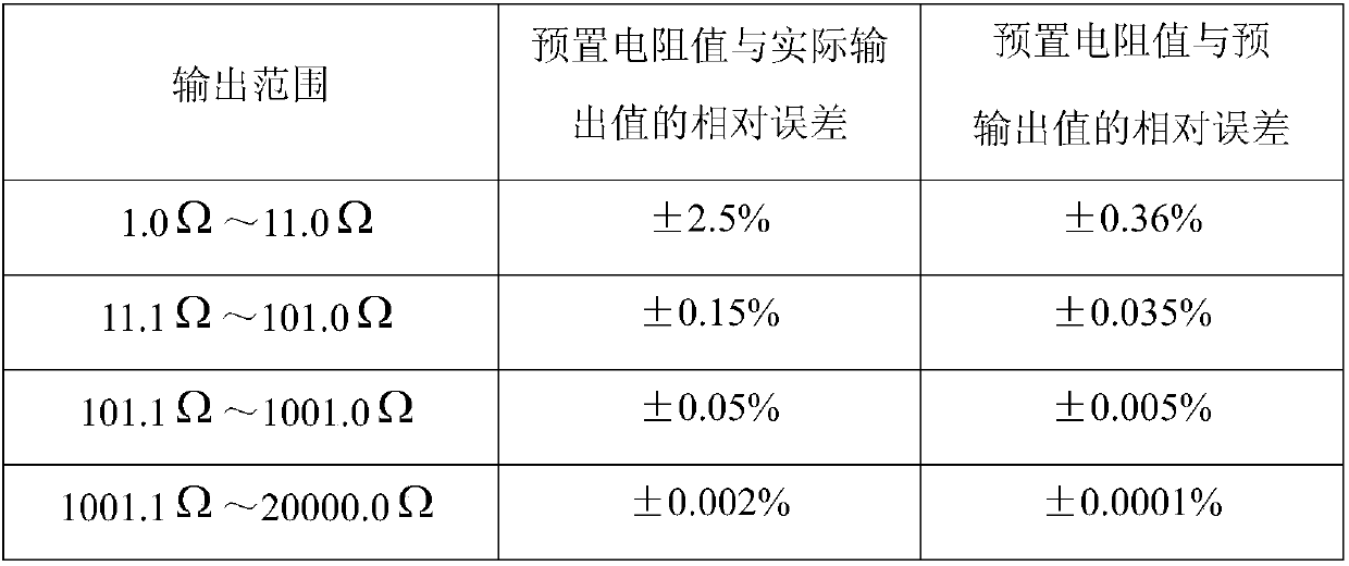
[0045] Set the output range of the passive resistance generator to 1.0Ω~20.0KΩ, the resolution is 0.1Ω, the resistance used is 0.01Ω~10KΩ, and the series resistance is selected from four bases with nominal values of 1, 2, 2 and 5 , and 25 resistors of magnitude W={0.01, 0.1, 1, 10, 100, 1000, 10000} M=1, 2, . . . , 25. The method for optimizing the resistance combination mode of the resistance network in this embodiment is:
[0046] (1) defined by The composed matrix is x 11 、x 21 ~x 74 corresponding to The nominal value corresponding to X is K ni =[K ni 1,K ni 2,K ni 3,K ni 4];
[0047] (2) by X 标 Establish the ideal output equation R 理 =∑(S1×K ni 4, S2×K ni 3, S3×K ni 2, S4×K ni 1)×W, where S1, S2, S3, and S4 are 1, 2, 2, and 5 respectively, and the resistance combination is coded according to the ideal output equation, and the resistance combination coding table shown in Table 1 is established;
[0048] (3) Obtain the matrix U=[N of all resistance...
Embodiment 2
[0053] Set the output range of the passive resistance generator to 1.0Ω~1.0MΩ, and the resolution to 0.1Ω. The series resistors use four bases with nominal values of 1, 2, 4, and 8, and the order of magnitude W={0.01, 0.1 , 1, 10, 100, 1000, 10000, 100000} 32 resistors M=1,2,...,32. The method for optimizing the resistance combination mode of the resistance network in this embodiment is:
[0054] (1) defined by The composed matrix is x 11 、x 21 ~x 84 corresponding to The nominal value corresponding to X is K ni =[K ni 1,K ni 2,K ni 3,K ni 4];
[0055] (2) by X 标Establish the ideal output equation R 理 =∑(S1×K ni 4, S2×K ni 3, S3×K ni 2, S4×K ni 1)×W, wherein S1, S2, S3, and S4 are 1, 2, 4, and 8 respectively, and the resistance combination is coded according to the ideal output equation, and the resistance combination coding table shown in Table 2 is established;
PUM
Abstract
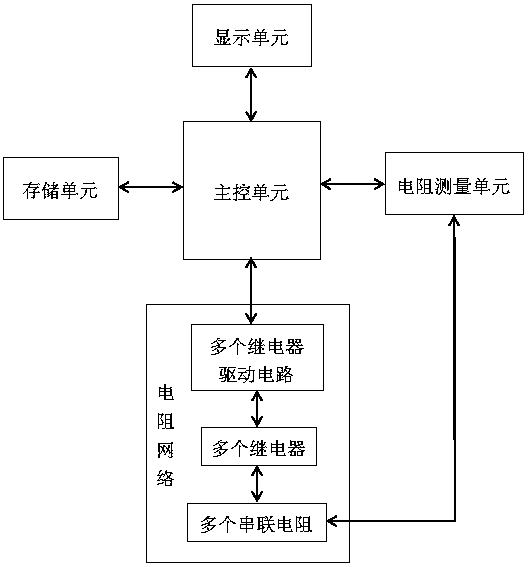
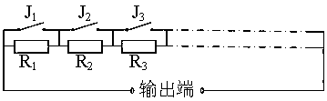
The invention discloses a high-precision passive resistance generator for compensating hardware error influence. The high-precision passive resistance generator comprises a main control unit, a resistor network and a resistance measuring unit, wherein the resistor network and the resistance measuring unit are connected with the main control unit; the resistor network comprises M serially connected resistors, M normally closed relays which are connected with the resistors in parallel, and M relay driving circuits for controlling corresponding relays to be opened and closed; the relay driving circuits are connected with the main control unit; the main control unit is used for receiving resistance of the resistors in the resistor network and used for confirming an optimal resistance combination mode N by using a hardware error compensation method according to preset resistance R; the resistance is measured by the resistance measuring units; corresponding relays are controlled by the relay driving circuits to be opened and closed, resistors which are connected in parallel correspondingly are in an opened or short circuit state, and passive resistance can be output to compensate hardware error influence. By adopting the high-precision passive resistance generator, the problems that the output precision of a conventional passive resistance generator completely depends on resistance precision and is low in output precision are solved, and the requirement on the precision of a passive resistor in practical use can be met.
Description
technical field [0001] The invention relates to the fields of instrument calibration, circuit testing and the like, and relates to a high-precision passive resistance generator for compensating the influence of hardware errors. Background technique [0002] As an important reference source in the fields of instrumentation calibration and circuit testing, the resistance generator's accuracy is particularly important. Existing high-precision resistance generators mainly include electronic active adjustable resistors and digital passive resistors. Among them, the electronic active adjustable resistor is based on Ohm's law, and the processor converts the input preset resistance value into a corresponding control signal to control the range conversion circuit and the gain setting circuit to change the overall output voltage of the circuit, thereby realizing Intelligent adjustment of resistance value. This resistance generation method uses a DAC chip to achieve voltagegain ampl...
Claims
Application Information
Patent Timeline
Application Date:The date an application was filed.
Publication Date:The date a patent or application was officially published.
First Publication Date:The earliest publication date of a patent with the same application number.
Issue Date:Publication date of the patent grant document.
PCT Entry Date:The Entry date of PCT National Phase.
Estimated Expiry Date:The statutory expiry date of a patent right according to the Patent Law, and it is the longest term of protection that the patent right can achieve without the termination of the patent right due to other reasons(Term extension factor has been taken into account ).
Invalid Date:Actual expiry date is based on effective date or publication date of legal transaction data of invalid patent.

