Rotary Electric Machine Stator And Manufacturing Method Of Same

A technology of a rotating electrical machine and a manufacturing method, which is applied in the manufacture of motor generators, stator/rotor bodies, and electric components, etc., can solve problems such as increased cost, inability to ensure insulation, and complex manufacturing processes.

Inactive Publication Date: 2016-07-06
TOYOTA JIDOSHA KK
View PDF5 Cites 14 Cited by
  • Summary
  • Abstract
  • Description
  • Claims
  • Application Information

AI Technical Summary

Problems solved by technology

This may cause the thickness of the insulating coating to become thinner at positions corresponding to the corners of the stepped portion, making it impossible to ensure insulation
Furthermore, as described in JP2012-161153A and JP2004-137903A, if a process of further forming an insulating layer by coating with another resin material is added, the manufacturing process of the stator becomes complicated and its cost increases

Method used


Image

  • Rotary Electric Machine Stator And Manufacturing Method Of Same
  • Rotary Electric Machine Stator And Manufacturing Method Of Same
  • Rotary Electric Machine Stator And Manufacturing Method Of Same

Examples


Embodiment Construction

[0029] Embodiments of the present invention will be described in detail below with reference to the drawings. In this description, specific shapes, materials, values, directions, and the like are examples to facilitate the understanding of the present invention, and may be appropriately modified according to uses, purposes, specifications, and the like. Also, where the following description includes a plurality of embodiments or modifications, it is assumed from the beginning that their features are used in combination appropriately.

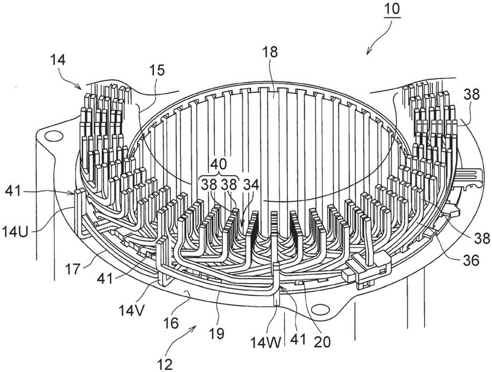
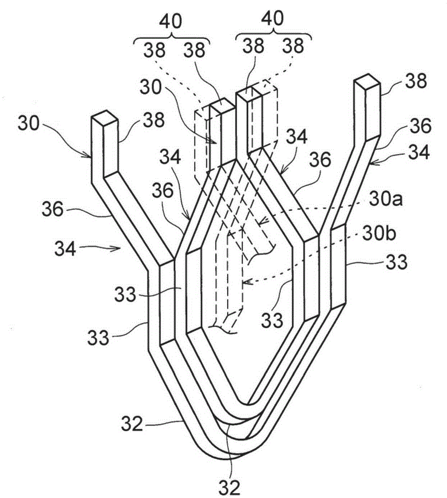
[0030] figure 1 is a partial perspective view of a stator (hereinafter simply referred to as "stator" as appropriate) 10 of a rotating electric machine according to an embodiment of the present invention. also, figure 2 is a perspective view of the segmented conductors 30 constituting the stator coil.

[0031] Such as figure 1 As shown, the stator 10 includes a stator core 12 and stator coils 14 . The stator core 12 is, for example, a subs...


PUM


Abstract

A rotary electric machine stator includes: a stator core including slots; a stator coil wound around the stator core by joining end portions of a plurality of segment conductors placed to be inserted into each of the slots; and an insulating layer (54) provided around the end portions including a joining portion at the end portions of the plurality of segment conductors. The segment conductor is constituted by an electric conductor (44) and an insulation coating (46) that covers the electric conductor (44). A conductor exposed portion (50) in which the insulation coating (46) is removed is formed in each of those end portions (38) of the segment conductors which are joined to each other. The insulating layer (54) is formed to be attached onto an insulating member (52) that covers a stepped portion (48) formed in a boundary between the insulation coating (46) and the conductor exposed portion (50).

Description

technical field [0001] The present invention relates to a rotary electric machine stator configured such that end portions of segment conductors configured to be inserted into slots of a stator core are joined to each other so as to form a stator coil, and a manufacturing method thereof. Background technique [0002] As a related technology of the present invention, for example, Japanese Patent Application Publication No. 2012-161153 (JP2012-161153A) describes: In a stator of a rotary electric machine, the stator includes an annular stator core having a plurality of slots in the circumferential direction and a structure In the stator winding so that the terminal portions of the plurality of segment conductors configured to be inserted into the slots are connected to each other by welding and wound around the stator core—the junction portion where the terminal portions of the plurality of segment conductors join is is covered with a first insulating coating made of powdered r...

Claims


Application Information

Patent Timeline
Patent Type & Authority Applications(China)
IPC IPC(8): H02K3/38H02K1/16H02K15/02H02K15/10
CPCH02K1/16H02K3/38H02K15/02H02K15/085H02K15/10H02K2203/00H02K15/105H02K15/12
Inventor 真杉丰水谷哲志
Owner TOYOTA JIDOSHA KK
Why Eureka
Try Eureka