Rotary electric machine

a rotary electric machine and axial length technology, applied in the direction of magnet circuit shape/form/construction, solid insulation application, windings, etc., can solve the problems of inability to achieve axial length reduction and increase stator axial length, and achieve the effect of reducing the size of the automotive electric motor and suppressing the stator axial length increas

Inactive Publication Date: 2013-12-17
MITSUBISHI ELECTRIC CORP
View PDF7 Cites 12 Cited by
  • Summary
  • Abstract
  • Description
  • Claims
  • Application Information

AI Technical Summary

Benefits of technology

[0009]The present invention aims to solve the above problems and an object of the present invention is to provide a rotary electric machine that suppresses axial length increases in a stator and ensures sufficient electrical insulation between leader lines that are led out from a radially outer end portion and a radially inner end portion in a concentrated winding coil that is wound into an edgewise winding to enable reductions in size to be achieved.
[0011]According to the present invention, because a portion of an insulating sheet extends so as to cover a coil end portion, and a conductor wire that projects outward from a radially inner end portion of a concentrated winding coil is bent, and is led radially outward parallel to the coil end portion that is covered by the portion of the insulating sheet, sufficient electrical insulation is ensured between the second leader line that projects outward from the radially inner end portion of the concentrated winding coil and a radially outer end portion. Thus, it is not necessary to separate the second leader line that projects outward from the radially inner end portion of the concentrated winding coil inordinately from the coil end portion of the concentrated winding coil to be led radially outward parallel to the coil end portion, enabling axial length increases in the stator to be suppressed, thereby enabling reductions in the size of the automotive electric motor.

Problems solved by technology

Thus, in order to ensure sufficient insulating distance between the two leader lines, it is necessary to increase the distance between the leader line that is led out from the winding finish end portion and the coil end portion, and one problem has been that axial length of the stator is increased, and reductions in size cannot be achieved.

Method used


Image

  • Rotary electric machine
  • Rotary electric machine
  • Rotary electric machine

Examples


embodiment 1

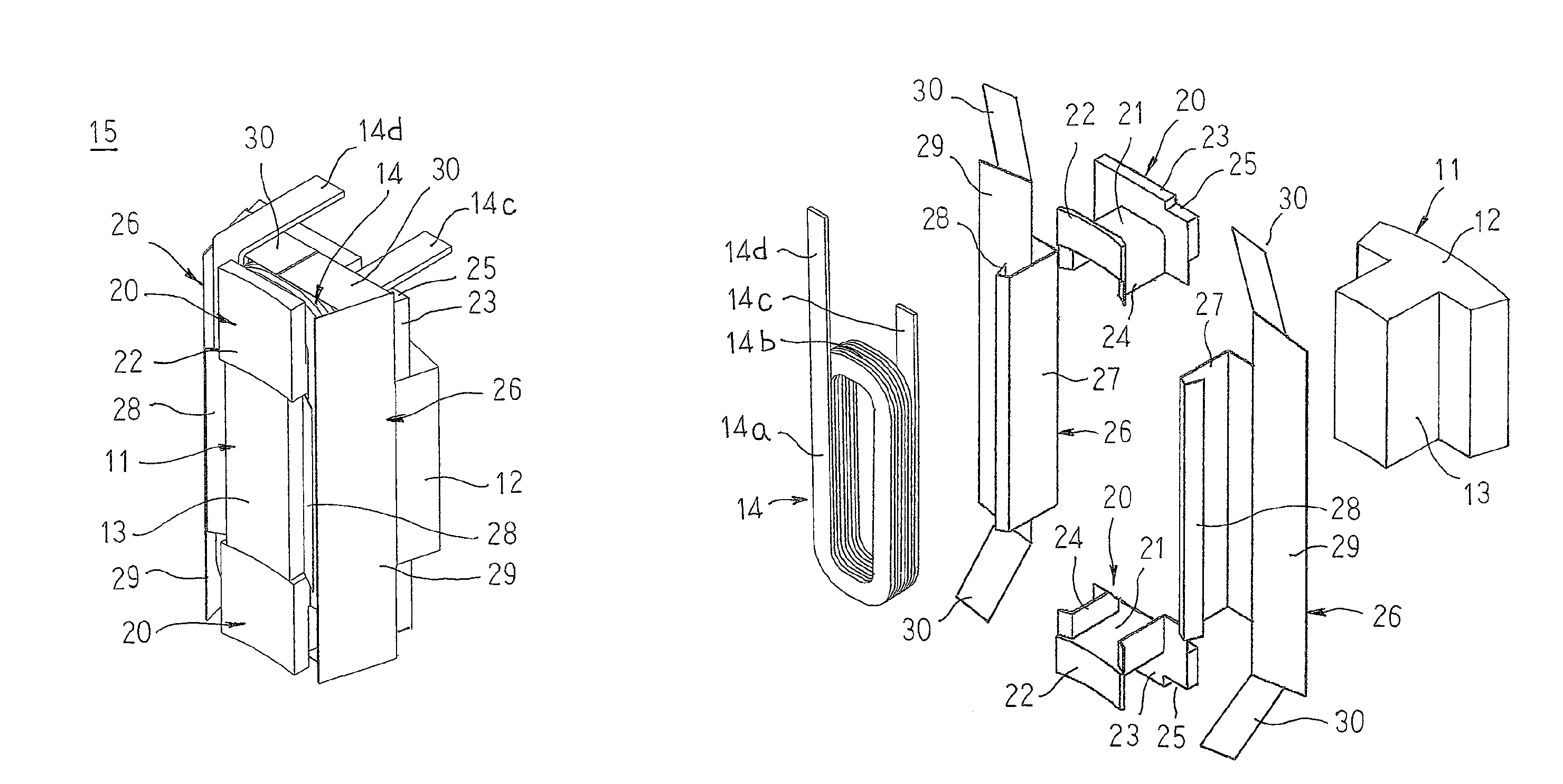
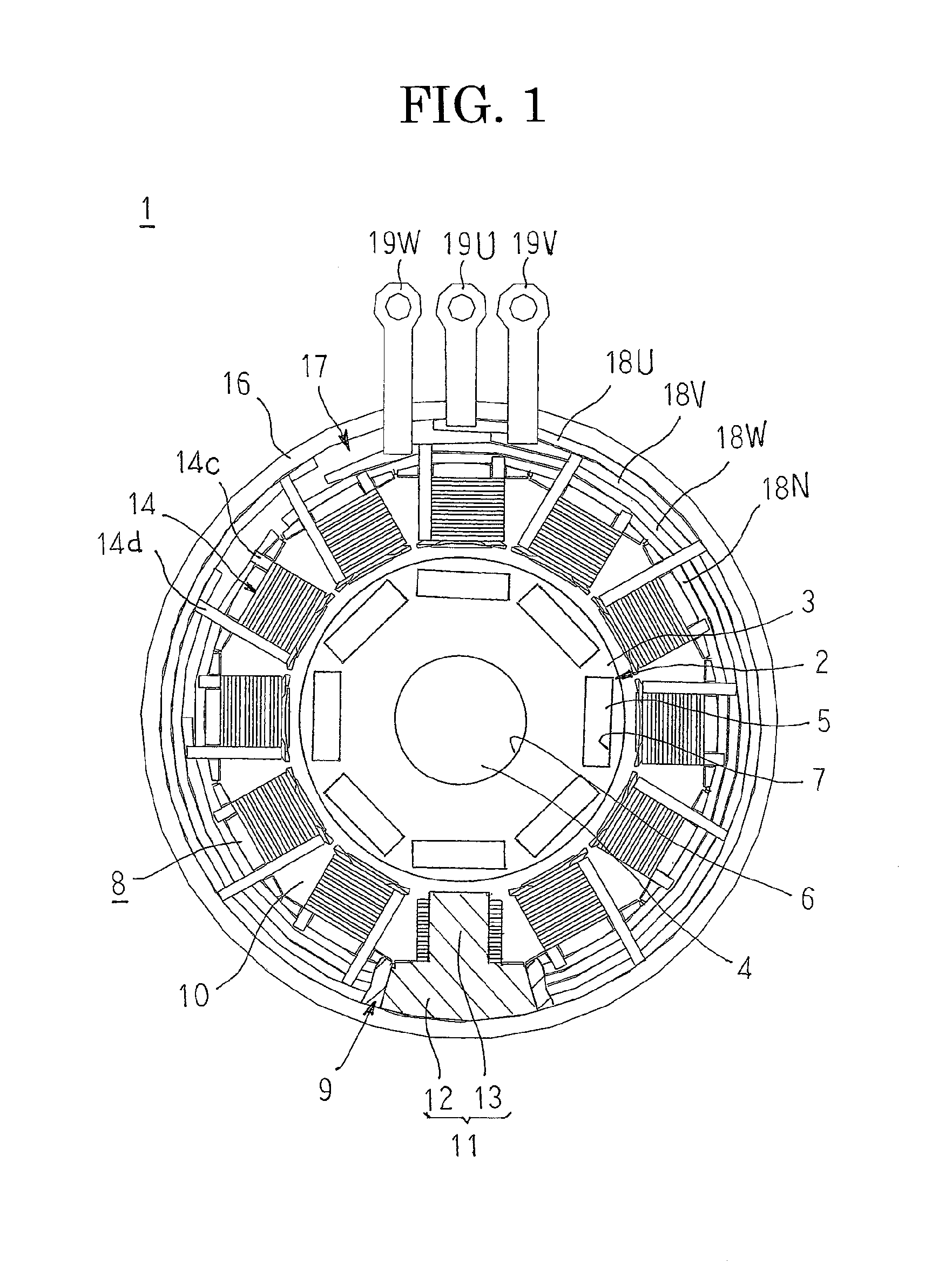
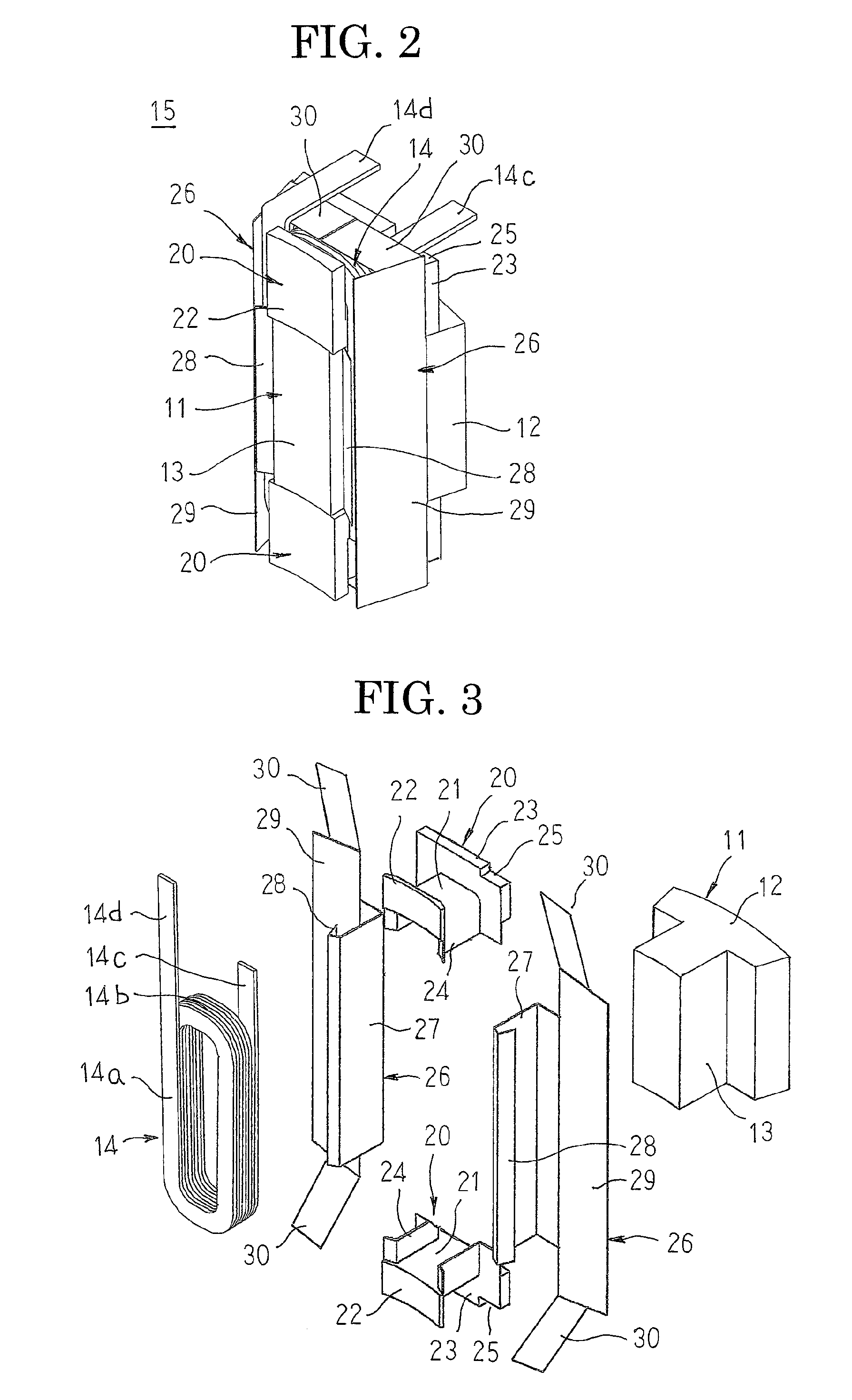
[0020]FIG. 1 is a partially cut away end elevation that shows an automotive electric motor according to Embodiment 1 of the present invention, FIG. 2 is a perspective that shows a coil assembly in the automotive electric motor according to Embodiment 1 of the present invention, FIG. 3 is an exploded perspective that explains a configuration of the coil assembly in the automotive electric motor according to Embodiment 1 of the present invention, FIGS. 4A through 4C are process perspectives that explain an assembly method for the coil assembly in the automotive electric motor according to Embodiment 1 of the present invention, and FIGS. 5A and 5B are process perspectives that explain the assembly method for the coil assembly in the automotive electric motor according to Embodiment 1 of the present invention. Moreover, in FIG. 1, the automotive electric motor is shown with a bobbin and insulating sheets omitted for convenience.

[0021]In FIGS. 1 and 2, an automotive electric motor 1 that...

embodiment 2

[0042]FIG. 6 is an exploded perspective that explains a configuration of a coil assembly in an automotive electric motor according to Embodiment 2 of the present invention, and FIGS. 7A through 7C are process perspectives that explain an assembly method for the coil assembly in the automotive electric motor according to Embodiment 2 of the present invention.

[0043]In FIG. 6, a coil assembly 15A is constituted by a core segment 11, a concentrated winding coil 14, a pair of bobbins 20, and insulating sheets 26 and 26A. In addition to a protective portion 27, a first cover portion 28, a second cover portion 29, and a third cover portion 30, the insulating sheet 26A has: a fourth cover portion 31 that functions as a second extended portion that is extended circumferentially from the second cover portion 29, and that is folded over so as to overlap with the third cover portion to cover a coil end portion 14b of a concentrated winding coil 14. Here, a direction of projection of the fourth ...


PUM


Abstract

The concentrated winding coil is mounted onto a tooth such that a coil end portion is housed inside a concave space that is formed by the trunk portion and first and second guide portions at two axial ends of the tooth. Third cover portions of an insulating sheet that is disposed on two circumferential sides of the tooth are folded over so as to overlap with each other and extend so as to cover the coil end portion of the concentrated winding coil, and a second leader line that projects outward from a radially inner end portion of the concentrated winding coil is bent and led radially outward parallel to the coil end portion that is covered by the third cover portions.

Description

BACKGROUND OF THE INVENTION[0001]1. Field of the Invention[0002]The present invention relates to a rotary electric machine that is used in an automotive electric motor, etc., that is mounted to an automobile, for example, and particularly relates to an insulating construction for a concentrated winding that is wound edgewise onto teeth of a stator.[0003]2. Description of the Related Art[0004]Conventional stators in which concentrated windings are applied to pole tooth portions of a stator core include insulating sheets that axially cover concave slot portions that are formed on two sides of the pole tooth portions, and straight portions and coil end portions of winding bodies are insulated by the insulating sheets (see Patent Literature 1, for example).[0005]Patent Literature 1: Japanese Patent Laid-Open No. 2003-61286 (Gazette)[0006]In conventional stators, the straight portions and the coil end portions of the winding bodies are covered and insulated by the insulating sheets, but ...

Claims


Application Information

Patent Timeline
Patent Type & Authority Patents(United States)
IPC IPC(8): H02K1/18H02K3/34H02K15/10
CPCH02K3/522H02K2203/12
Inventor YOSHIDA, SHINICHIROINOUE, MASAYAOKAMOTO, SHOGO
Owner MITSUBISHI ELECTRIC CORP
Why Eureka
Try Eureka