Method of insulation and framing

a technology of framing and insulation, which is applied in the field of framing construction, can solve the problems of limited insulation which can be stuffed into the wall, difficulty in ensuring the safety of the structure, so as to facilitate the proper insulating of the wall, reduce heating and cooling costs, and simple and effective

Inactive Publication Date: 2001-08-07
RINGLEIN HAROLD +2
View PDF4 Cites 14 Cited by
  • Summary
  • Abstract
  • Description
  • Claims
  • Application Information

AI Technical Summary

Benefits of technology

It is an object of this invention to disclose a method of framing construction which results in a substantially more air tight structure. It is an object of this invention to disclose a method of framing which facilitates more adequately insulating walls. It is an overall objective of this invention to disclose a method of construction which will culminate in a substantially more thermally efficient structure which will have substantially reduced heating and cooling costs. It is yet a further object of this invention to disclose a simple and effective method of framing which uses standard materials in standard and familiar ways. A method which framers will be able to readily adapt to with minimal learning time and with minimal investment in inventory.

Problems solved by technology

The insulation which can be stuffed into the wall is limited by the width of the studs.
When the wall is covered with an air impervious sheeting it cannot be made air tight because of the openings in its face which must be made for the electrical outlet and switch boxes.
Sometimes the exterior wall contains water lines, Because of the inadequate insulation between the walls exterior side and the water lines, freezing of the water lines may be a problem.
However the problem with this approach is that the shroud must be penetrated by interconnecting electrical cables.

Method used


Image

  • Method of insulation and framing
  • Method of insulation and framing

Examples


Embodiment Construction

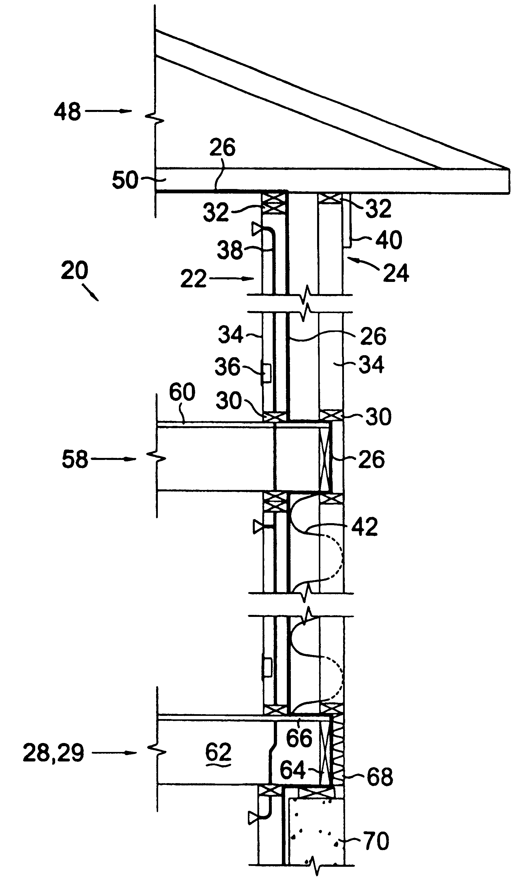
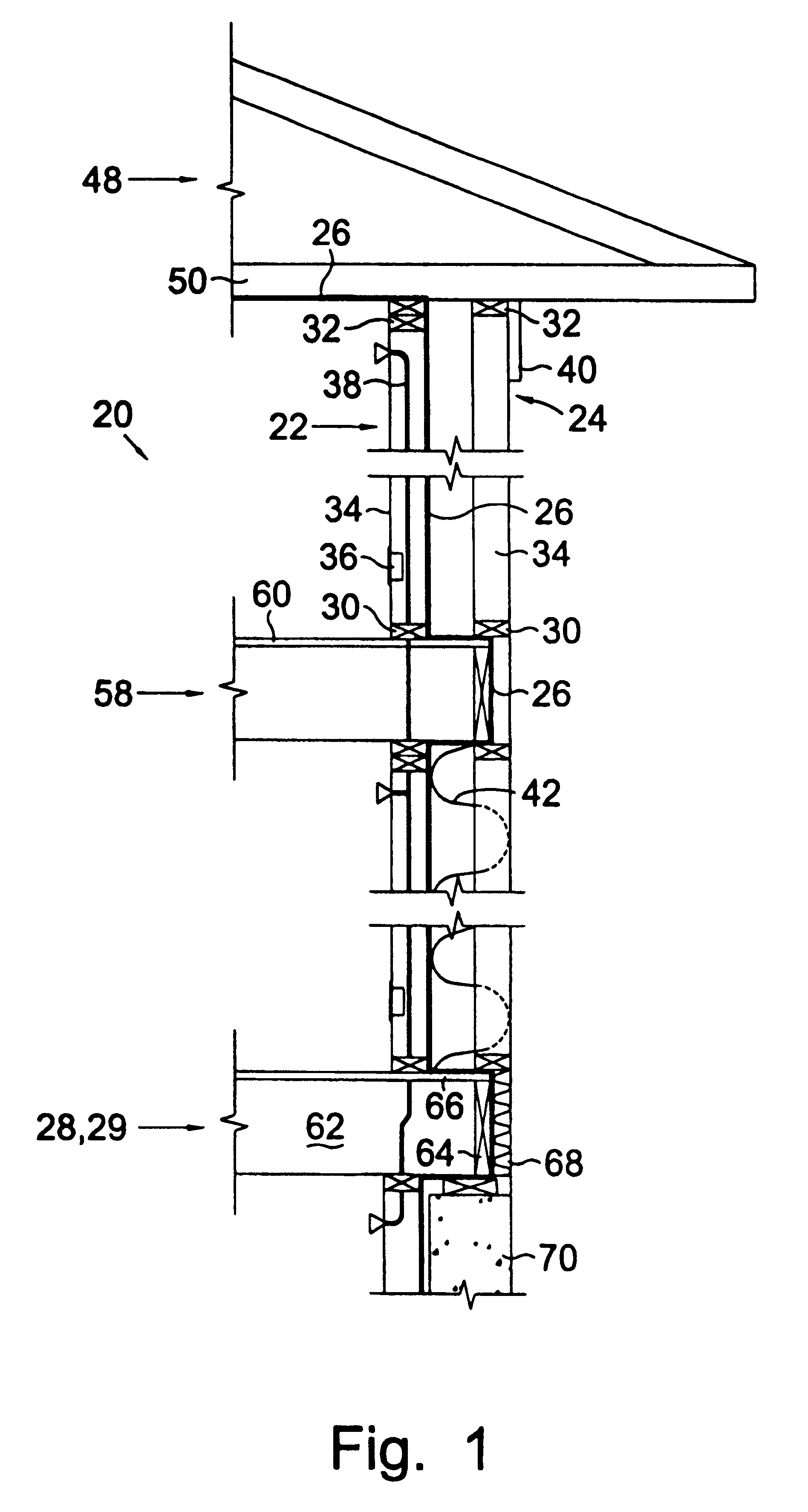
Turning now to the drawings and more particularly to FIG. 1 we have a cross sectional view of a wall framing system 20 showing the double wall 22,24 framing method having a continuous unbroken vapor barrier 26. A method of framing and seating an exterior double wall on a supporting structure 28 comprises the following steps: erecting an inner wall 22 having a footer 30, a top plate 32, and spaced upright studs 34, along an inner edge portion of the supporting structure 28; covering the exterior side portion of the inner wall with a vapor barrier 26 so that electrical wiring 36 and plumbing 38 may be run within the interior wall 22 without penetrating the vapor barrier 26; erecting an outer wall 24 having a footer 30, a top plate 32, and spaced upright studs 34 along an outer edge portion of the supporting structure 28 parallel to and spaced from the inner wall 22, said outer wall 24 used to carry an exterior building wall covering 40 after insulation 42 which is positioned between t...


PUM


Abstract

A method of construction which produces an air tight structure which is capable of being insulated to high R values. The method comprises the following steps: erecting an inner wall having a footer, a top plate, and spaced upright studs, along an inner edge portion of the supporting structure; covering the exterior side portion of the inner wall with a vapor barrier so that electrical wiring and plumbing may be run within the interior wall without penetrating the vapor barrier; erecting an outer wall having a footer, a top plate, and spaced upright studs along an outer edge portion of the supporting structure parallel to and spaced from the inner wall, said outer wall used to carry an exterior building wall covering after insulation which is positioned between the walls and between the studs of the outer wall; and, erecting a supported structure on top of the top side portion of the walls. The vapor barrier is extended over the top portion of one of the walls so that it may be subsequently tied into the vapor barrier extending along the supported structure.

Description

This invention relates to thermally efficient construction. More particularly this invention relates to a method of construction which produces an air tight structure which is capable of being insulated to high R values.Conventional residential construction uses framed exterior walls which comprise a single row of 2.times.4 or 2.times.6 studs. The insulation which can be stuffed into the wall is limited by the width of the studs. Above door and window openings headers are required for structural strength and there is no room for insulation. The exterior walls also contain electrical outlet and switch boxes which are interconnected with wire cables. When the wall is covered with an air impervious sheeting it cannot be made air tight because of the openings in its face which must be made for the electrical outlet and switch boxes. Sometimes the exterior wall contains water lines, Because of the inadequate insulation between the walls exterior side and the water lines, freezing of the ...

Claims


Application Information

Patent Timeline
Patent Type & Authority Patents(United States)
IPC IPC(8): E04B1/26
CPCE04B1/26
Inventor RINGLEIN, HAROLDRINGLEIN, ALFRED C.MORGAN, JAMES
Owner RINGLEIN HAROLD
Why Eureka
Try Eureka