Resin-mold core and reactor using the same

a technology of reactor and core, which is applied in the direction of transformer/inductance details, fixed inductances, and inductances, etc., can solve the problems of difficult to ensure insulation, restrict the drawing direction of the terminal, and difficult to downsize the reactor, etc., and achieve the effect of downsizing the reactor

Active Publication Date: 2015-02-05
TAMURA KK
View PDF5 Cites 12 Cited by
  • Summary
  • Abstract
  • Description
  • Claims
  • Application Information

AI Technical Summary

Benefits of technology

[0024]According to the present disclosure, the openings exposing the magnetic core are not provided in the yoke portion of the resin-mold core. Hence, even if a terminal is disposed on this part, a sufficient insulation between the terminal and the magnetic core is ensured. As a result, it becomes possible to draw the terminal to the exterior from the yoke portion near the coil end, thereby enabling downsizing of the reactor.
[0025]In particular, when resin-made terminal stage having the terminal molded is disposed at this part, and the terminal stage and the resin portion of the resin-mold core are fastened, the fastening work of the terminal stage to the resin-mold core and a joining work of the terminal to the coil end can be carried out easily.

Problems solved by technology

Hence, when the terminal is drawn to the yoke-portion side from the end of the coil, it is difficult to ensure the insulation because of the opening 102 formed at the yoke portion.
When, however, the terminal is disposed so as to avoid the opening 102, the drawing direction of the terminal is restricted, and the downsizing of the reactor becomes difficult.

Method used


Image

  • Resin-mold core and reactor using the same
  • Resin-mold core and reactor using the same
  • Resin-mold core and reactor using the same

Examples


first embodiment

1. First Embodiment

[0041]A first embodiment of the present disclosure will be explained in detail below with reference to FIGS. 1 and 2.

[0042](1) Structure

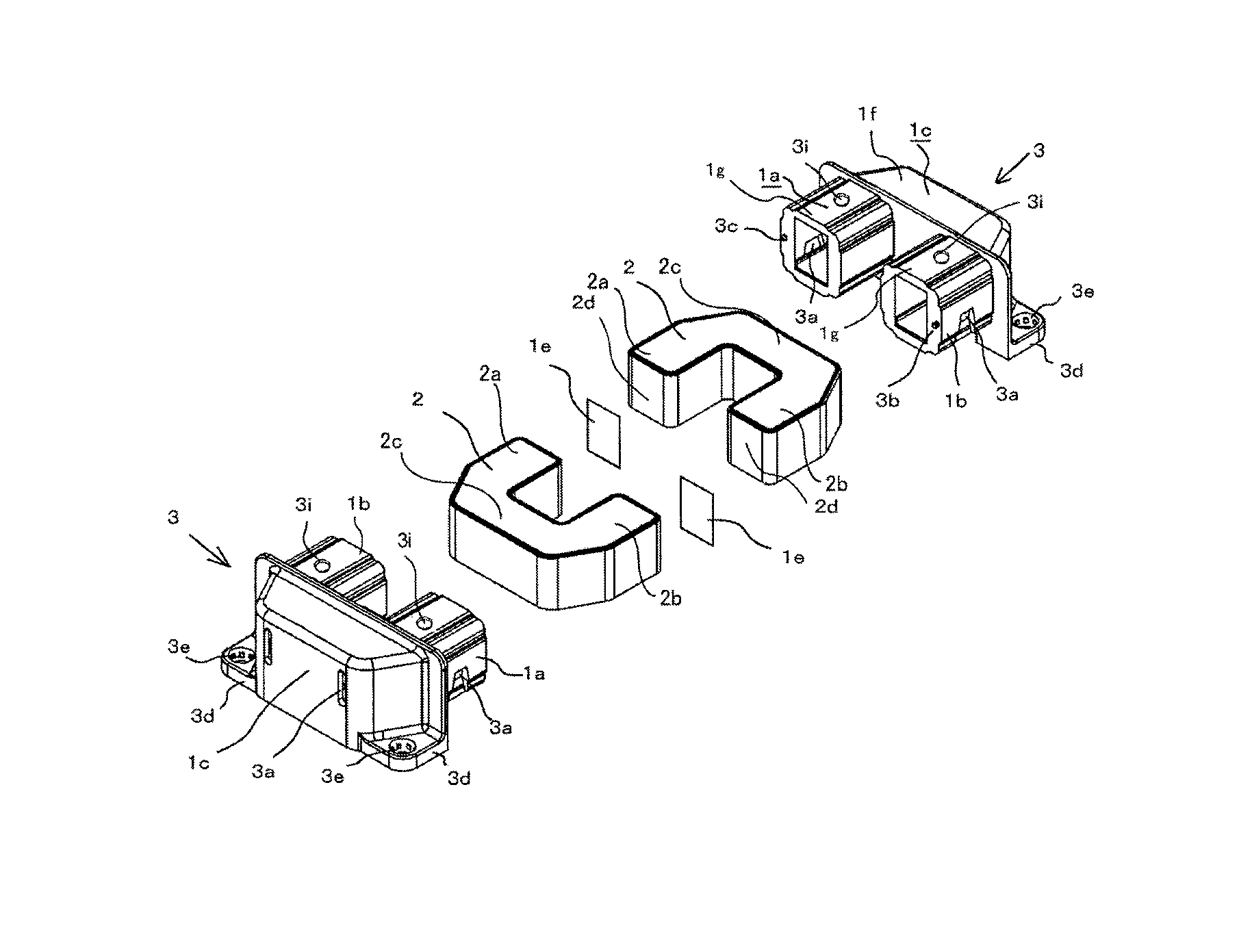
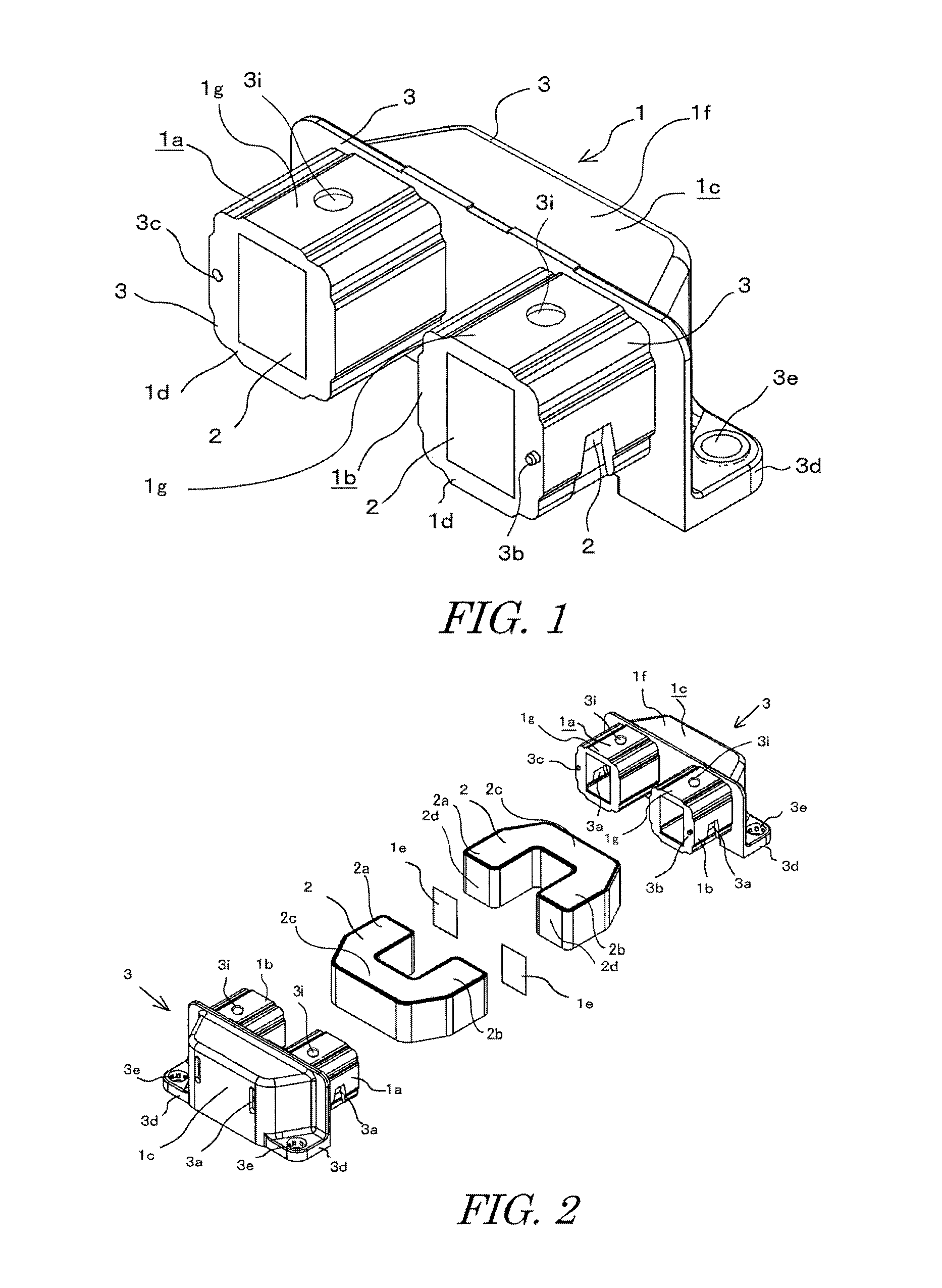
[0043]As illustrated in FIG. 1, a resin-mold core 1 of this embodiment is formed in a U-shape having right and left leg portions 1a, 1b each formed in a rectangular column shape, and a trapezoidal yoke portion 1c connecting those. When a reactor is formed using this U-shaped resin-mold core 1, as illustrated in FIG. 2, end faces 1d of the respective leg portions1a, 1b of the two U-shaped resin-mold cores 1 are abutted with spacers 1e to form an annular core. The U-shaped resin-mold cores 1 in FIG. 1 correspond to a “resin-mold core divided into two pieces” in appended claims.

[0044]The U-shaped resin-mold core 1 includes a magnetic core 2 likewise formed in a U-shape, and a resin-mold component (hereinafter, referred to as a mold component) 3 provided so as to cover the entire circumference of the magnetic core 2. The magnetic core...

second embodiment

2. Second Embodiment

[0057]A reactor according to a second embodiment will be explained with reference to FIGS. 3 to 6. The same component as that of the first embodiment will be denoted by the same reference numeral, and the duplicated explanation thereof will be omitted.

[0058](1) Structure

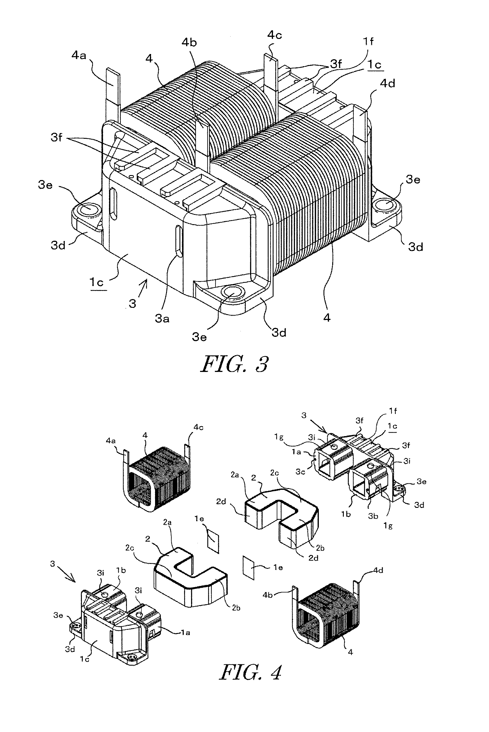
[0059]As illustrated in FIGS. 3 and 4, a reactor of this embodiment has two divided resin-mold cores 1 of the first embodiment combined to form an annular-shaped resin-mold core. Coils 4 are attached around the outer circumferences of the leg portions, and terminals 5a to 5d to electrically connect the coil ends to a component outside of the reactor are provided.

[0060]That is, the coils 4 are attached to the respective outer circumferences of the right and left leg portions 1a, 1b of the resin-mold core 1. The coil 4 has a rectangular wire wound so as to be laminated in the thickness direction, and tabular both ends 4a to 4d of the respective coils 4 protrude to the upper space beyond the yoke por...

third embodiment

3. Third Embodiment

[0074]A reactor of a third embodiment will be explained with reference to FIGS. 7 to 14. The similar component to that of the first embodiment will be denoted by the same reference numeral, and the duplicated explanation thereof will be omitted. According to this embodiment, the terminals 5a to 5d are molded in a resin-made terminal stage 6, and the terminal stage 6 and the resin-mold core 1 are fastened together to connect the coil ends 4a to 4d with the terminals 5a to 5d.

[0075]The resin-mold core 1 utilized in this embodiment basically employs the same structure as that of the resin-mold core 1 of the first embodiment, but as illustrated in FIGS. 7 and 8, a protrusion 3g for positioning the terminal stage 6, and a screw hole 3h near the protrusion 3g and to fasten the terminal stage 6 to the resin-mold core 1 are provided on and in a side of the upper face of the yoke portion 1c.

[0076]The pair of brackets 3d are formed at the lower part of the resin-mold core...


PUM

PropertyMeasurementUnit
magneticaaaaaaaaaa
timeaaaaaaaaaa
circumferenceaaaaaaaaaa

Abstract

A resin-mold core includes right and left leg portions, and a yoke portion interconnecting those. The resin-mold core includes a magnetic core, and a mold component having the magnetic core embedded therein by molding. Openings where the magnetic core in the mold component is exposed are formed in multiple faces of the mold component that are upper, lower, front, rear, and right and left faces. Apart of the yoke portion of the resin-mold core corresponding to a location where terminals are drawn to the exterior of the core from coils attached to the outer circumferences of the leg portions of the core has no opening formed in the multiple faces of the mold component. Positioning members to coaxially align the leg portions of the opposing resin-mold core are formed in abutting faces of the leg portions of the resin-mold core.

Description

CROSS-REFERENCE TO RELATED APPLICATIONS[0001]This application is based upon and claims the benefit of priority from Japanese Patent Application NO. 2013-161927, filed on Aug. 4, 2013; the entire contents of which are incorporated herein by reference.BACKGROUND OF THE INVENTION[0002]1. Field of the Invention[0003]The present disclosure relates to a resin-mold core having a magnetic core embedded in a resin-mold component by molding like insert molding, and a reactor using the same.[0004]2. Description of the Related Art[0005]As a reactor utilized for, for example, an in-vehicle booster circuit, one which has a resin bobbin disposed at a leg portion of an annular magnetic core, and which has a coil wound around this bobbin is conventionally known. According to this type of reactor, as a technology of disposing the bobbin around the magnetic core, insert molding of the magnetic core in the resin bobbin is known.[0006]In this case, not only the leg portion of the magnetic core is covere...

Claims


Application Information

Patent Timeline
Patent Type & Authority Applications(United States)
IPC IPC(8): H01F27/26H01F3/00
CPCH01F3/00H01F27/263H01F27/29H01F27/306H01F37/00H01F27/24H01F27/2823H01F41/0246
Inventor NAKATSU, RYONINOMIYA, TOSHIKAZUMAENO, KENSUKE
Owner TAMURA KK
Why Eureka
Try Eureka