Drive device, electronic equipment, drive control program, and drive signal-generating method

A driving signal and driving device technology, applied in the direction of AC motor control, control system, fluid using vibration, etc., can solve the problem that it is difficult to provide tactile sensation

Inactive Publication Date: 2016-07-06
FUJITSU LTD
View PDF6 Cites 4 Cited by
  • Summary
  • Abstract
  • Description
  • Claims
  • Application Information

AI Technical Summary

Problems solved by technology

[0004] However, in conventional devices, it is difficult to provide a good tactile feeling when the resonance frequency of the vibration generating device changes according to the acceleration amplitude

Method used


Image

  • Drive device, electronic equipment, drive control program, and drive signal-generating method
  • Drive device, electronic equipment, drive control program, and drive signal-generating method
  • Drive device, electronic equipment, drive control program, and drive signal-generating method

Examples


Embodiment approach 1

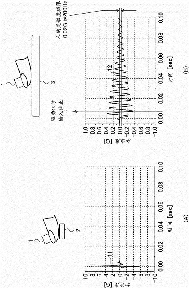
[0043] Below, refer to figure 1 The outline of Embodiment 1 will be described. figure 1 It is a figure explaining the outline|summary of Embodiment 1.

[0044] figure 1 (A) is a diagram showing the acceleration waveform 11 of the vibration generated when the accelerometer 1 is attached to a person's finger and the button 2 is pressed. figure 1 (B) is a diagram showing the acceleration waveform 12 of vibration generated when the accelerometer 1 is attached to a human finger and the touch panel 3 equipped with an LRA (Linear Resonant Actuator: Linear Resonant Actuator) is touched. exist figure 1 In the example of , the button 2 is, for example, a metal dome button. In addition, the button 2 and the touch panel 3 are provided on the electronic device.

[0045] The vibration represented by the waveform 11 decays rapidly within one to several cycles. On the other hand, the vibration represented by the waveform 12 continues until the free vibration due to the natural frequency...

Embodiment approach 2

[0266] Hereinafter, Embodiment 2 will be described with reference to the drawings. Embodiment 2 is an example in which resonance frequency f0 of LRA 140 is a value measured in a state incorporated in electronic device 100 . In the description of Embodiment 2, only the points of difference from Embodiment 1 will be described. In addition, in Embodiment 2, components having the same functions as those in Embodiment 1 are given the same reference numerals as those used in the description of Embodiment 1, and description thereof will be omitted.

[0267] In Embodiment 2, the resonance frequency f0' of the touch panel 120 in the state which incorporated LRA140 in the electronic device 100 was measured. Furthermore, in Embodiment 2, the resonance frequency f0' is used when calculating the frequency f1 of the drive signal Z.

[0268] Figure 33It is a figure explaining the driving device of Embodiment 2. Drive device 200A of Embodiment 2 has CPU 210A and memory 220A.

[0269] Th...


PUM


Abstract

Provided are a drive device, electronic equipment, drive control program, and drive signal-generating method, which are capable of producing a sensation that corresponds to operation. The drive device comprises: a storage unit, which stores waveform data representing a drive signal that is a sine wave satisfying frequency (f1) = (m / n) * q(t) with respect to the time characteristic q(t) of the resonance frequency and excites a vibration-generating device, for which the resonance frequency varies in a range comprising the rated value (f0) from a first to a second resonance frequency according to the acceleration amplitude, (m) times ((m) and (n) being mutually differing non-0 natural numbers), or a drive signal for exciting the vibration-generating device (m / 2) * (a) times ((a) being a non-0 natural number)((m) and (n) being mutually differing positive odd numbers); and a drive-processing unit for outputting the drive signal to the vibration-generating device. The time characteristic q(t) is a time characteristic that is a sine wave satisfying frequency (f1) = (m / n) * (f2) and is obtained by driving the vibration-generating device with a drive signal that excites the vibration-generating device (m) times when (m) is not equal to (n) or a drive signal that excites the vibration-generating device (m / 2) * (a) times ((m) and (n) being mutually differing positive odd numbers).

Description

technical field [0001] The present invention relates to a drive device for driving a vibration generating device, an electronic device, a drive control program, and a method for generating a drive signal. Background technique [0002] In the past, there has been a user / mechanical interface comprising: a panel having a surface and capable of supporting flexural waves; a touch-sensitive input device associated with said surface; Unit of force transducer for force feedback. The force is in the form of a pulse against the panel, the pulse is in the form of a modulated signal that provides a button click feeling to the user's fingertip, and the modulated signal is a reference carrier frequency having a range of 150 to 750 Hz and It lasts for at least 10 ms (for example, refer to Patent Document 1). [0003] Patent Document 1: Japanese Patent Laid-Open No. 2012-20284 [0004] However, in conventional devices, it is difficult to provide a good tactile feeling when the resonance ...

Claims


Application Information

Patent Timeline
Patent Type & Authority Applications(China)
IPC IPC(8): B06B1/04B06B1/06G06F3/041
CPCG06F3/016B06B1/045B06B1/06G06F3/041H02P25/032
Inventor 谷中圣志远藤康浩矢吹彰彦
Owner FUJITSU LTD
Why Eureka
Try Eureka