Supercharge Your Innovation With Domain-Expert AI Agents!

Automobile body positioning support device

A technology for positioning support and automobile body, applied in auxiliary devices, injection devices, auxiliary welding equipment, etc., can solve the problems of complex operation, affecting production efficiency, limiting the types of vehicle models, etc., and achieves convenient use, simple and novel structure and accurate positioning. Effect

Inactive Publication Date: 2018-02-16
力帆科技(集团)股份有限公司
View PDF8 Cites 1 Cited by
  • Summary
  • Abstract
  • Description
  • Claims
  • Application Information

AI Technical Summary

Problems solved by technology

[0003] In painting, welding and other processes, the car body is usually conveyed on the production line by skids. When multiple models are produced on the same line, due to the different positioning points of the car bodies of each model, some positioning supports that can be switched are generally made, but each The difference in the position of the car model support is small. Even if the switching mechanism is used, the types of car models are limited. In addition, when switching models, manual or program-controlled adjustments to the support are required, and the operation is more complicated, which affects production efficiency.

Method used


Image

  • Automobile body positioning support device
  • Automobile body positioning support device
  • Automobile body positioning support device

Examples


Embodiment Construction

[0026] The present invention will be further described below in conjunction with embodiment and accompanying drawing.

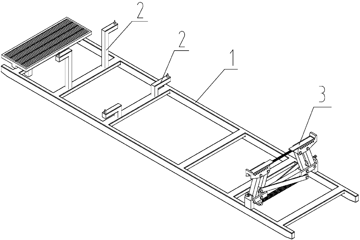
[0027] Such as figure 1 A car body positioning support device shown includes a pry body 1 with a rectangular frame structure. At least two sets of positioning columns 2 are installed on the front end of the pry body 1. On the side beam, a tapered positioning pin (not shown) is provided at the upper end of the positioning column 2, and a longitudinal beam bracket 3 is installed at the rear end of the skid body 1.

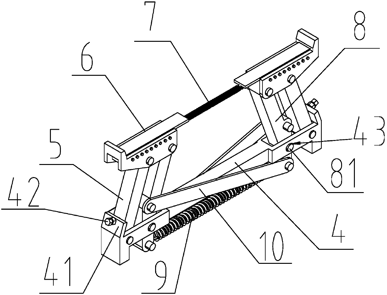
[0028] figure 2 and image 3 The specific structure of the longitudinal beam bracket 3 is shown, and the longitudinal beam bracket 3 includes a connecting beam 4 horizontally fixed on the rear end of the skid body 1 along the width direction of the skid body 1, and the two ends of the connecting beam 4 are respectively connected to a support arm 5. The two support arms 5 are arranged symmetrically. The lower end of each support arm 5 is hingedly...


PUM


Abstract

The invention discloses an automobile body positioning and supporting device. The device comprises a prying body, two supporting arms, two positioning blocks, two synchronization arms and a synchronization connecting rod, wherein positioning columns are arranged at the two sides of the front end of the prying body, a longitudinal beam bracket is arranged at the rear end of the prying body, and the longitudinal beam bracket comprises a connecting beam transversely fixed to the rear end of the prying body; the two supporting arms are symmetrically mounted at the two ends of the connecting beam, and the lower end of each supporting arm is hinged to the connecting beam; the two positioning blocks are hinged to the upper ends of the two supporting arms respectively, and a return tension spring is connected between the two positioning blocks; the two synchronization arms are symmetrically mounted at the two ends of the connecting beam, each synchronization arm is parallel to the corresponding supporting arm located at the same side, the upper end of each synchronization arm is hinged to the corresponding positioning block, the middle of each synchronization arm is hinged to the connecting beam, and the lower ends of the two synchronization arms are connected through a return spring; the two ends of the synchronization connecting rod are connected to the two synchronization arms respectively, so that the two synchronization arms rotate synchronously. According to the automobile body positioning and supporting device, an automobile body longitudinal beam can be used as the supporting point, the device can be adapted to positioning and supporting of multiple models, switching is not needed, self-adaptation positioning is achieved, and the device has the advantages of being simple and novel in structure, convenient to use, accurate in positioning and the like.

Description

technical field [0001] The invention relates to an automobile production equipment, in particular to an automobile body positioning support device. Background technique [0002] With the continuous improvement of people's consumption level, in order to cater to the individual needs of consumers, major automobile manufacturers will design a variety of models for consumers to choose from. In order to save production space and improve equipment utilization, manufacturers usually adopt the method of multi-model collinear production, that is, two or more models are put into the same production line for production. [0003] In painting, welding and other processes, the car body is usually conveyed on the production line by skids. When multiple models are produced on the same line, due to the different positioning points of the car bodies of each model, some positioning supports that can be switched are generally made, but each The difference in the position of the vehicle support...

Claims


Application Information

Patent Timeline
Patent Type & Authority Patents(China)
IPC IPC(8): B05B13/02B23K37/04
CPCB05B13/0285B23K37/0435
Inventor 那春林
Owner 力帆科技(集团)股份有限公司
Features
  • R&D
  • Intellectual Property
  • Life Sciences
  • Materials
  • Tech Scout
  • Unparalleled Data Quality
  • Higher Quality Content
  • 60% Fewer Hallucinations
Learn More