A reed moving raising mechanism

A technology of raising mechanism and reed movement, which is applied in looms, textiles, textiles and papermaking, etc., can solve the problems affecting the stability of looms, safety performance, short service life of the pendulum rod, and large force on the pendulum rod. The effect of stable weft, small maintenance and stable performance

Active Publication Date: 2017-04-26
JIANGSU YOUCHENG CNC TECH CO LTD
View PDF1 Cites 0 Cited by
  • Summary
  • Abstract
  • Description
  • Claims
  • Application Information

AI Technical Summary

Problems solved by technology

[0002] Existing reed moving towel looms, in order to meet the requirements of different terry fluffing heights, need to realize long and short weft beating by changing the swing angle of the reed, such as a kind of reed moving air-jet towel loom with patent No. 201420200844. The first and second pendulum rods drive the sley legs, and the rotation points of the first and second pendulum rods with a fixed angle are changed by the loop crankshaft to drive and control the sley legs to achieve different angles of rotation and beat-up of the sley legs, but the first 1. The second pendulum itself fixes the included angle, and its connection point is used as the rotation point to control the rotation period of the coil crankshaft. When the coil coil cycle is controlled, the rotation axis of the coil crankshaft is misaligned with the hinge point of the first and second pendulum rods on the coil crankshaft. The force of the pendulum at the rotation point is large. In the long-term and high-speed beating environment, the service life of the pendulum is short, which affects the stability and safety of the loom.

Method used


Image

  • A reed moving raising mechanism

Examples


Embodiment Construction

[0014] The present invention will be further described below in conjunction with drawings and embodiments.

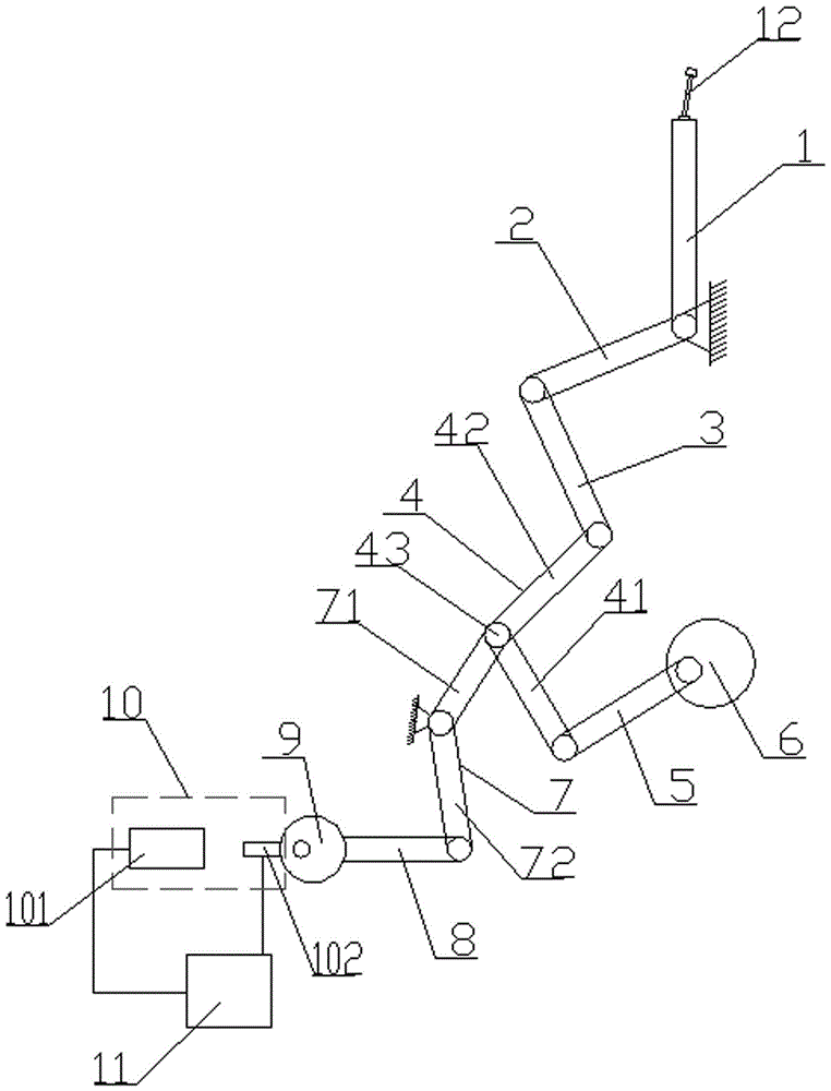
[0015] figure 1 Middle: A reed moving fluffing mechanism includes reed 12, sley foot 1, sley foot drive lever 2, sley foot drive link 3, fixed angle reversing lever group 4, power rod drive link 5, eccentric Driving mechanism 6, adjustable and fixed angle control rod group 7, eccentric connecting rod 8, numerical control actuator 9, origin signal acquisition mechanism 10 and control electric box 11, eccentric driving mechanism 6 hinged power rod driving connecting rod 5 at one end, power rod The other end of the drive link 5 is hinged to one end of the first power rod 41 of the reversing rod group 4 at a fixed angle, and the other end of the first power rod 41 is connected to one end of the second power rod 42 at an adjustable fixed angle and has a power rod hinge point 43. The other end of the second power rod 42 is hinged to one end of the sley foot drive link 3, the...


PUM


Abstract

The invention relates to a reed moving and fluffing mechanism.An eccentric drive mechanism is hinged to one end of a power rod drive connection rod, the other end of the power rod drive connection rod is hinged to one end of a fixed included angle reserving rod set, the other end of the fixed included angle reserving rod set is hinged to one end of a sley sword drive connection rod, the other end of the sley sword drive connection rod is hinged to one end of a sley sword drive lever, and the other end of the sley sword drive lever is connected with a sley sword adjustable fixed included angle; the non-end point of the fixed included angle reserving rod set is hinged to one end of an adjustable fixed included angle control rod set, the middle of the adjustable fixed included angle control rod set is movably hinged to a loom frame, the other end of the adjustable fixed included angle control rod set is hinged to one end of an eccentric connection rod, the other end of the eccentric connection rod is connected with a numerical control execution mechanism, the numerical control execution mechanism is provided with an original point signal acquisition mechanism, and both the numerical control execution mechanism and the original point signal acquisition mechanism are connected with a control electricity box.

Description

technical field [0001] The invention relates to a loom, in particular to a reed moving raising mechanism of the loom. Background technique [0002] In the existing reed moving towel loom, in order to meet the requirements of different pile heights, it is necessary to change the swing angle of the reed to achieve long and short beating. For example, a reed moving air jet towel loom with a patent number of 201420200844.6 adopts a fixed angle The first and second pendulum rods drive the sley legs, and the rotation points of the first and second pendulum rods with a fixed angle are changed by the looping crankshaft to drive and control the sley legs to achieve different angles of rotation and beat-up of the sley legs, but the first 1. The second pendulum itself fixes the included angle, and its connection point is used as the rotation point to control the rotation period of the coil crankshaft. When controlling the coil coil cycle, the rotation axis of the coil crankshaft is mis...

Claims


Application Information

Patent Timeline
Patent Type & Authority Patents(China)
IPC IPC(8): D03D49/60
CPCD03D49/60
Inventor 王勇
Owner JIANGSU YOUCHENG CNC TECH CO LTD
Why Eureka
Try Eureka