Mechanical turnout applied to high-temperature super conducting magnetic floating system and steering method

A high-temperature superconducting and magnetic levitation technology, applied in roads, tracks, buildings, etc., to achieve good magnetic field uniformity, uniform magnetic field, and reliable performance

Active Publication Date: 2016-07-13
SOUTHWEST JIAOTONG UNIV
View PDF9 Cites 19 Cited by
  • Summary
  • Abstract
  • Description
  • Claims
  • Application Information

AI Technical Summary

Problems solved by technology

[0004] The object of the present invention is to provide a mechanical switch and a steering method applied to a high-temperature sup

Method used


Image

  • Mechanical turnout applied to high-temperature super conducting magnetic floating system and steering method
  • Mechanical turnout applied to high-temperature super conducting magnetic floating system and steering method
  • Mechanical turnout applied to high-temperature super conducting magnetic floating system and steering method

Examples


Embodiment 1

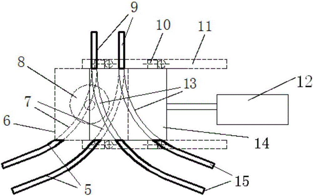
[0043]This embodiment is applied to the docking of one line with two lines in different directions, and the docking is completed by the first diverting rail 13 and the second diverting rail 7 respectively. The first steering rail 13 is fixed on the first translation transmission plate 14, and the first translation transmission plate 14 is fixedly connected to the first translation driving member 12, and is driven in translation by the first translation driving member 12; the second steering rail 7 is fixed on the first lifting On the transmission plate 6 , the first lifting transmission plate 6 is fixedly connected with the first lifting driving member 8 , and is driven by the first lifting driving member 8 . Wherein, the first steering rail 13 is located next to the docking position, and reaches the docking point of the two lines by means of translation, and the second steering rail 7 is directly below the docking position, and directly reaches the docking point of the two lin...

Embodiment 2

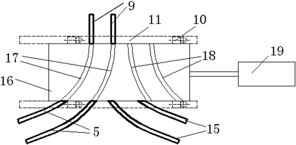
[0048] This embodiment is also applied to the connection between one line and two lines in different directions. image 3 The structure is shown, which is actually a structural diagram of a direct translation switch. For convenience of distinction, the steering rails are defined as the third steering rail 17 and the fourth steering rail 18 . In this embodiment, the third steering rail 17 and the fourth steering rail 18 move synchronously, and one drive assembly is used, specifically, the third steering rail 17 and the fourth steering rail 18 are fixed on the second translation transmission plate 16, On the transmission plate, there is a "eight" character, and the two steering rails all have a connection end connected to the main line 9, and the connecting line of the two connection ends is parallel to the translation direction of the second translation transmission plate 16. The second translation transmission plate 16 is connected with the second translation driving member 1...

Embodiment 3

[0052] This embodiment is applied to the docking of four lines that intersect each other and converge at the intersection point, and the four lines that cross each other are connected in pairs. Figure 4 This structure is shown, which is actually a structural diagram of the lifting rotary switch. For convenience of description, the steering rail is defined as the fifth steering rail 27, and the fifth steering rail 27 is fixed on the first rotary transmission plate 23, and the first rotary transmission plate 23 is connected with the second lift drive member 28, the first rotary drive member respectively. 24 connected, driven by the lift of the second lift drive member 28, and driven by the rotation of the first rotary drive member 24. The connecting line between the first line 22 and the third line 20 , the connecting line between the second line 26 and the fourth line 25 that need to be connected intersect with each other, and the intersection point is located on the fifth div...


PUM


Abstract

The invention relates to the technical field of steering, in particular to a mechanical turnout applied to a high-temperature super conducting magnetic floating system and a steering method. The mechanical turnout comprises a steering magnetic track component, wherein the steering magnetic track component comprises at least two steering magnetic tracks; the width of each steering magnetic track is the same with that of a permanent magnet track; each steering magnetic track is fixed on a corresponding driving plate and is positioned above the driving plate; the driving plate is connected with a driving component; the driving component drives the driving plate to translate, rotate and/or lift. The mechanical turnout adopts mechanical driving force to drive switching magnetic tracks, tracks are uniform in magnetic field after butt joint, and the electromagnetic resistance during operation is reduced. In addition, compared with certain electromagnetic turnout, the mechanical turnout has the advantages that mechanical force driving is adopted, the performance is more reliable, and the magnetic field uniformity is better.

Description

technical field [0001] The invention relates to steering technology, in particular to a mechanical switch and a steering method applied to a high-temperature superconducting magnetic levitation system. Background technique [0002] figure 1 It is a schematic diagram of the structure of a high-temperature superconducting maglev train. The train body 1 relies on the interaction force between the permanent magnet track and the superconductor 2 to achieve levitation. The permanent magnetic track 3 is mainly composed of fragile permanent magnetic materials, so the reversing of the high-temperature superconducting maglev train cannot be realized by the deformation of the track like the conventional track system. [0003] Turnout is an indispensable equipment for rail transit to realize line conversion. At present, there are few studies on the turnout equipment of HTS maglev trains, and so far only a small amount of research involves HTS maglev turnouts. The currently proposed h...

Claims


Application Information

Patent Timeline
IPC IPC(8): E01B25/34
CPCE01B25/34
Inventor 林群煦邓自刚张娅郑珺
Owner SOUTHWEST JIAOTONG UNIV
Why Eureka
Try Eureka