Electronic controlled hydraulic mount

An electronically controlled hydraulic and suspension technology, applied in the field of auto parts, can solve the problems of not meeting the shock absorption requirements, high cost, complex structure, etc., and achieve the effect of simple structure, low cost and good reliability

Inactive Publication Date: 2016-07-13
哈尔滨通用液压机械制造有限公司
View PDF2 Cites 10 Cited by
  • Summary
  • Abstract
  • Description
  • Claims
  • Application Information

AI Technical Summary

Problems solved by technology

Although the two mounts disclosed above have a good damping effect, they all have a serious deficiency, that is, the existing hydraulic mounts usually only have a good damping effect in a certain frequency range. Can not meet the shock absorption requirements in the whole working range of the car
The newly proposed active mount technology makes up for the lack of high-frequency performance of traditional hydraulic mounts through active actuators for shock absorption in the high-frequency range, but its structure is complex and the cost is high

Method used


Image

  • Electronic controlled hydraulic mount
  • Electronic controlled hydraulic mount

Examples


Embodiment Construction

[0014] The present invention will be further described below in conjunction with the accompanying drawings.

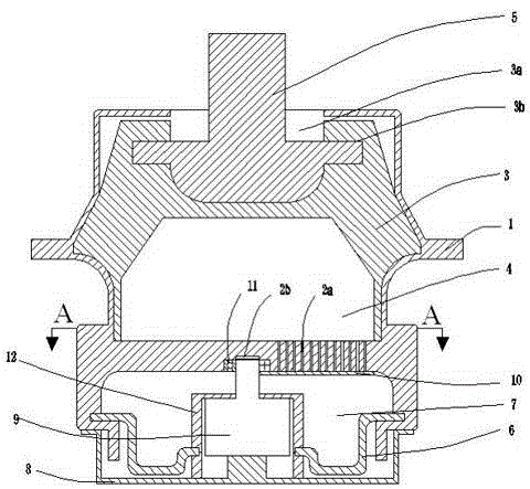
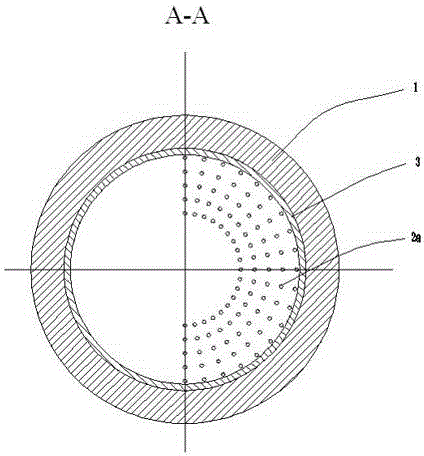
[0015] See figure 1 and figure 2 : An electronically controlled hydraulic mount, comprising a shell base 1, a rubber spring 3, a metal frame 5 and a base film 6, the shell base 1 is divided into two cavities up and down by a partition 2, and the partition 2 is located on the shell base 1, and the partition 2 is integrated with the shell base 1, and a rubber spring 3 is arranged in the upper cavity of the shell base 1, and the rubber spring 3 and the partition 2 form a closed upper liquid chamber 4 , a metal skeleton 5 is fixed on the rubber spring 3, and the upper end of the metal skeleton 5 protrudes from the shell base 1, that is, a skeleton installation hole 3a is opened in the center of the upper part of the rubber spring 3, and a skeleton installation hole 3a is inside the skeleton installation hole 3a. There is an annular card slot 3b, the section of the metal...


PUM


Abstract

The invention discloses an electronic controlled hydraulic mount, comprising a housing base, a rubber spring, a metallic framework, and a bottom film. The middle part of the housing base is provided with a partition. The partition and the rubber spring, and the partition and the bottom film respectively form a sealed upper liquid chamber and a lower liquid chamber. A part of the partition is provided with orifices communicating the upper liquid chamber with the lower liquid chamber. The lower liquid chamber is internally provided with a motor. The output shaft of the motor is fixedly sleeved with a throttling valve board. The upper surface of the throttling valve board is abutted against the lower surface of the partition. When the motor is started, the throttling valve board can control on-off of the orifices. The electronic controlled hydraulic mount uses the motor to control on-off of the orifices, so as to control dynamic characteristics of the hydraulic mount, and the hydraulic mount satisfies requirements of vibration reduction in different working conditions.

Description

technical field [0001] The invention relates to auto parts, in particular to an electronically controlled hydraulic mount. Background technique [0002] Automotive engine mount refers to the elastic connection system between the engine powertrain and the vehicle frame. The design of the system's vibration damping performance is directly related to the transmission of engine vibration to the vehicle body, which affects the NVH performance of the vehicle. Specifically, the engine mount is an important part of the car, which is mainly used to reduce the vibration transmitted from the engine to the body, while controlling the displacement of the engine, resisting the torque of the engine, and reducing the vibration transmitted from the tire to the powertrain on potholes. shock. Therefore, it is required that the engine mount not only has a good vibration isolation capability, but also has a good ability to block shocks. Existing hydraulic mounts mainly include simple orifice t...

Claims


Application Information

Patent Timeline
Patent Type & Authority Applications(China)
IPC IPC(8): F16F13/08F16F9/14F16F9/44B60K5/12
Inventor 王利明
Owner 哈尔滨通用液压机械制造有限公司
Why Eureka
Try Eureka