Steamer refrigerating fluid collecting pipe supporting clamping seat

An evaporator and manifold technology, applied in the field of evaporator refrigerant manifold support clamps, can solve the problems of high difficulty, troublesome disassembly and assembly of manifolds, and high production costs, so as to reduce processing difficulty, improve assembly and disassembly efficiency, and reduce The effect of maintenance difficulty

Inactive Publication Date: 2016-07-13
焦伽
View PDF7 Cites 1 Cited by
  • Summary
  • Abstract
  • Description
  • Claims
  • Application Information

AI Technical Summary

Problems solved by technology

[0002] At present, the refrigerant manifold on the evaporator is usually fixed and welded to the side plate of the evaporator through a support to prevent the weld joints of the manifold and each branch coil from loosening. When it comes to pipes, it is troublesome to disassemble and assemble the manifold. At the same time, due to the complexity of the welding process, the overall manufacturing process of the evaporator is troublesome, with high production costs and low efficiency.
Although the domestic invention patent with the patent number of 201220350776.2 discloses a technical solution for the purpose of overcoming the above problems, in practical applications, in order to meet the requirements of use, the manifold still needs to be welded and fixed. Therefore, the The technical solution still fails to solve the deficiencies of the current technology

Method used


Image

  • Steamer refrigerating fluid collecting pipe supporting clamping seat
  • Steamer refrigerating fluid collecting pipe supporting clamping seat
  • Steamer refrigerating fluid collecting pipe supporting clamping seat

Examples


Embodiment Construction

[0010] The present invention will be further described below in conjunction with specific examples.

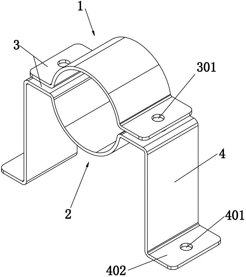
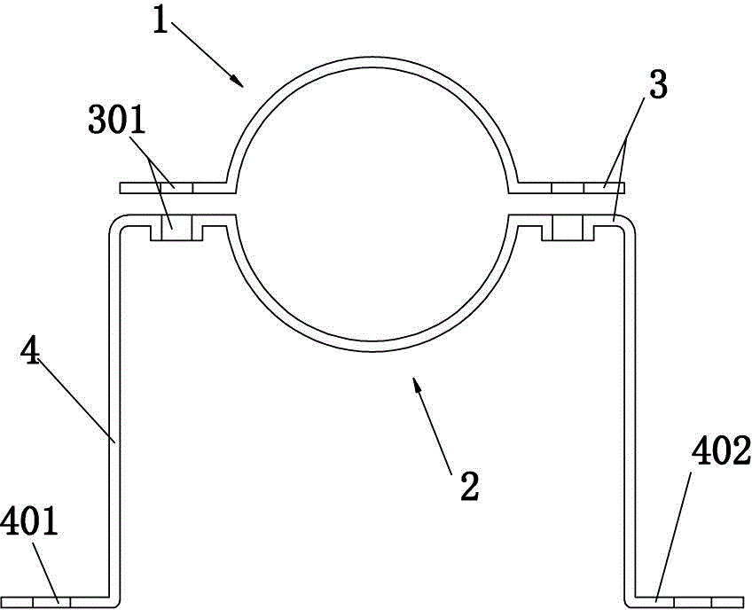
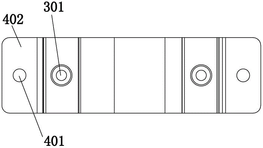
[0011] See attached figure 1 To attach image 3 As shown, the evaporator refrigerant manifold support clamp seat described in this embodiment includes a paired first clamp body 1 and a second clamp body 2, wherein the first clamp body 1 and the second clamp body 2. Each bending shape has a semi-circular arc structure with the same center, and the two semi-circular structures can be combined into a circular clamping part that can tighten the evaporator refrigerant confluence pipe. The two ends of each semi-circular arc structure are lugs 3 extending in opposite directions on the same straight line, and each lug 3 is provided with a mounting hole 301. The first clamping body 1 and the mounting holes 301 on the same side of the second clamping body 2 are correspondingly overlapped, bolts are tapped into the corresponding mounting holes 301 on the first clamping body 1 and the s...


PUM


Abstract

The invention provides a steamer refrigerating fluid collecting pipe supporting clamping seat comprising a first clamping body and a second clamping body paired with the first clamping body. The first and second clamping bodies bend to form arc-shaped structures sharing the same circle center; the two arc-shaped structure can be combined to form a round clamping part capable of clamping a steamer refrigerating fluid collecting pipe; two ends of each arc-shaped structure are lug sheets extending toward the opposite directions on the same straight line; an installation hole is formed on each lug sheet; a bolt is installed into relative installation holes of the first and second clamping bodies; and the first and second clamping bodies are clamped via cooperative nut, so an integral body is formed. With the above technical scheme and the specially-designed first and second clamping bodies, burn-welding for fixation of the steamer refrigerating fluid collecting pipe can be avoided, so processing difficulties can be reduced; the collecting pipe can be easily detached during the maintenance of pipelines; and maintenance difficulty can be lowered and collecting pipe detaching efficiency can be improved.

Description

technical field [0001] The invention relates to the technical field of evaporators, in particular to an evaporator refrigerant confluence pipe support clip seat. Background technique [0002] At present, the refrigerant manifold on the evaporator is usually fixed and welded to the side plate of the evaporator through a support to prevent the weld joints of the manifold and each branch coil from loosening. When it comes to pipelines, it is cumbersome and difficult to disassemble and assemble the manifold. At the same time, due to the complexity of the welding process, the overall manufacturing process of the evaporator is troublesome, with high production costs and low efficiency. Although the domestic invention patent with the patent number of 201220350776.2 discloses a technical solution for the purpose of overcoming the above problems, in practical applications, in order to meet the requirements of use, the manifold still needs to be welded and fixed. Therefore, the The t...

Claims


Application Information

Patent Timeline
Patent Type & Authority Applications(China)
IPC IPC(8): F16L3/10
Inventor 焦伽
Owner 焦伽
Why Eureka
Try Eureka