C-axis gyration center calibrating device and method based on double standard ball

A center of gyration and standard ball technology, applied in the direction of measuring devices, optical devices, instruments, etc., can solve the problems of mutual interference of mechanical parts, generation of a large number of chips, and inability to convert the spatial position to the machine tool coordinate system, so as to ensure the calibration accuracy, Guaranteeing the service life and avoiding the effect of mechanical parts interference

Active Publication Date: 2016-07-13
HARBIN INST OF TECH
View PDF4 Cites 18 Cited by
  • Summary
  • Abstract
  • Description
  • Claims
  • Application Information

AI Technical Summary

Problems solved by technology

[0002] At present, in the existing calibration methods of the center of rotation of the ultra-precision C-axis, most of them use a calibration device and method that combines a standard ball with a high-precision lever gauge or an inductance micrometer. Although such devices are used to achieve ultra-precision The calibration method of the center of rotation of the C-axis can accurately calibrate the spatial position of the center of rotation of the C-axis, but it cannot effectively transform the spatial position into the machine tool coordinate system
In the existing on-site detection system composed of white light confocal displacement sensors, a single standard ball is basically used to calibrate the centerline of the C-axis rotation, which requires the white light confocal displacement sensor to be fixed on the machine tool at all times, and cannot be removed from the machine tool. Therefore, it will bring inconvenience to the processing process and cause mutual interference between mechanical parts. At the same time, a large amount of chips will be generated during machine tool processing and cutting fluid needs to be sprayed, which will seriously affect the white light confocal displacement. Accuracy and service life of the sensor

Method used


Image

  • C-axis gyration center calibrating device and method based on double standard ball
  • C-axis gyration center calibrating device and method based on double standard ball
  • C-axis gyration center calibrating device and method based on double standard ball

Examples


Embodiment Construction

[0021] The technical solutions in the present invention will be clearly and completely described below in conjunction with the accompanying drawings in the embodiments of the present invention. Obviously, the described embodiments are only part of the embodiments of the invention, not all of them. Based on the present invention All other embodiments obtained by persons of ordinary skill in the art without creative efforts, all belong to the scope of protection of the present invention.

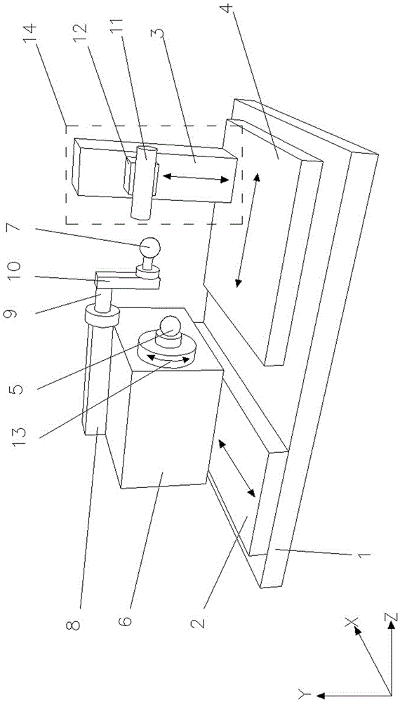
[0022] Such as figure 1 As shown, the present invention discloses a C-axis rotation center calibration device based on double standard balls, including X-axis guide rail 2, Z-axis guide rail 4, in-position detection mechanism 14, standard ball one 5, C-axis 6, standard ball two 7, Rectangular support base 8, 3R clamp 9, transition piece 10 and vacuum chuck 13; said in-position detection mechanism 14 includes a Y-axis lifting platform 3, a white light confocal displacement sensor 11 and a measu...


PUM


Abstract

Provided is a C-axis gyration center calibrating device and method based on double standard ball. A machine tool is provided with an X-axis guide rail and a Z-axis guide rail; a C axis is provided with a rectangular supporting seat having a 3R clamp, and a vacuum chuck having a first standard ball; a transition is in connection with the 3R clamp and a second standard ball; a measuring sensor fixing piece is located in front of a Y-axis lifting platform and is provided with a white light confocal displacement sensor. The method comprises: adjusting the position of the first standard ball, driving the C axis and the white light confocal displacement sensor, aligning the spherical crown position of the first standard ball, and recording a position PR (x,y) to be set as a gyration center position of the first standard ball; installing the 3R clamp and the second standard ball on the supporting seat, executing the spherical crown top point scanning on the second standard ball, adjusting the position of the white light confocal displacement sensor, allowing the white light confocal displacement sensor to align with the spherical crown position of the second standard ball, and recording a position PS (x,y) to be set as a reference center position of the second standard ball; and obtaining delta P through difference calculation. The device and method guarantee the service life of an on-line measurement device, and avoid mechanical part interference in a processing process.

Description

technical field [0001] The invention relates to a device and method for calibrating with double standard spheres. Background technique [0002] At present, in the existing calibration methods of the center of rotation of the ultra-precision C-axis, most of them use a calibration device and method that combines a standard ball with a high-precision lever gauge or an inductance micrometer. Although such devices are used to achieve ultra-precision The calibration method of the center of rotation of the C-axis can accurately calibrate the spatial position of the center of rotation of the C-axis, but it cannot effectively transform the spatial position into the machine tool coordinate system. In the existing on-site detection system composed of white light confocal displacement sensors, a single standard ball is basically used to calibrate the centerline of the C-axis rotation, which requires the white light confocal displacement sensor to be fixed on the machine tool at all time...

Claims


Application Information

Patent Timeline
Patent Type & Authority Applications(China)
IPC IPC(8): G01B11/27
CPCG01B11/27
Inventor 赵学森李国邹喜聪胡振江李增强孙涛
Owner HARBIN INST OF TECH
Why Eureka
Try Eureka