
Electric connector

An electrical connector and conductive terminal technology, applied in the field of electrical connectors, can solve the problems of increased cost, large volume, and large size of the base 31, and achieve the effects of ensuring positional accuracy, reducing manufacturing costs, and reducing the amount of materials

Active Publication Date: 2016-07-13
TYCO ELECTRONICS (SHANGHAI) CO LTD
View PDF6 Cites 1 Cited by
  • Summary
  • Abstract
  • Description
  • Claims
  • Application Information

AI Technical Summary

Problems solved by technology

However, the volume of the base 31 is large and requires a lot of copper, resulting in an increase in cost.
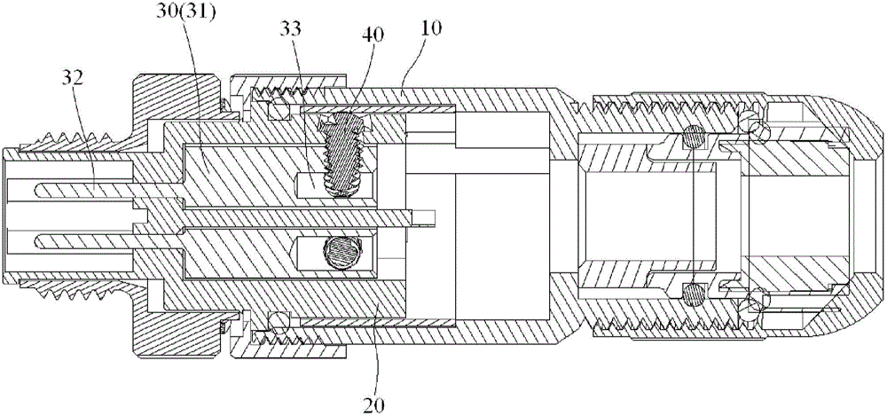
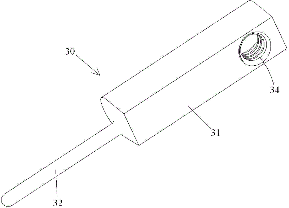
[0009] Also, please continue to see figure 1 and figure 2 , in the prior art, the longitudinal length of the base 31 is greater than half of the total longitudinal length of the entire conductive terminal 30, which leads to a larger volume of the base 31 and requires more materials, resulting in an increase in cost

Method used


Image

  • Electric connector
  • Electric connector
  • Electric connector

Examples


Embodiment Construction

[0039] The technical solutions of the present invention will be further specifically described below through the embodiments and in conjunction with the accompanying drawings. In the specification, the same or similar reference numerals designate the same or similar components. The following description of the embodiments of the present invention with reference to the accompanying drawings is intended to explain the general inventive concept of the present invention, but should not be construed as a limitation of the present invention.

[0040] In addition, in the following detailed description, for purposes of explanation, numerous specific details are set forth in order to provide a comprehensive understanding of the embodiments of the present disclosure. It may be evident, however, that one or more embodiments may be practiced without these specific details. In other instances, well-known structures and devices are shown in diagrammatic form to simplify the drawings.

[0...


PUM


Abstract

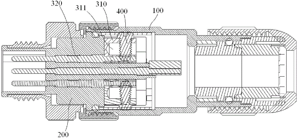
The invention discloses an electric connector, and the connector comprises a housing; an insulating main body which is stored in the housing; and at least one conductive terminal which is kept in the insulating main body. The conductive terminal comprises a substrate which is kept in the insulating main body; and a pin which is inserted into the substrate, and extends in a longitudinal direction to pass through the insulating main body. The pin is assembled in the insulating main body in a manner of interference fit. According to the invention, the pin of the conductive terminal is assembled in the insulating main body in the manner of interference fit, so the pin can be prevented from moving relative to the insulating main body, thereby guaranteeing the position precision of the pin.

Description

technical field [0001] The invention relates to an electric connector used for instruments, control equipment and electrical equipment. Background technique [0002] figure 1 A longitudinal sectional view of a conventional electrical connector is shown. figure 2 shown figure 1 A three-dimensional schematic diagram of the conductive terminal 30 in FIG. [0003] Such as figure 1 and figure 2 As shown, in the prior art, an electrical connector mainly includes a housing 10 , an insulating body 20 accommodated in the housing 10 and at least one conductive terminal 30 held in the insulating body 20 . [0004] In the existing technology, such as figure 1 and figure 2 As shown, there is a gap between the pin 32 of the conductive terminal 30 and the insulating body 20, and the two belong to a clearance fit. Therefore, the position accuracy of the pin 32 is difficult to control, and the position accuracy of the pin 32 after assembly is likely to exceed the technical specific...

Claims


Application Information

Patent Timeline
IPC IPC(8): H01R13/02H01R13/03H01R13/213H01R13/40
Inventor 高波徐祥汪浩赵期俊余建飞程志刚
Owner TYCO ELECTRONICS (SHANGHAI) CO LTD
Learn More