Centrifugal fixture

A technology of fixtures and clamping bodies, applied in the direction of chucks, etc., can solve the problems of high labor intensity, low clamping efficiency and low production efficiency of operators, and achieves time-saving and labor-saving disassembly of workpieces, low labor intensity and high production efficiency. Effect

Inactive Publication Date: 2016-07-20
CHONGQING BAOJUE MACHINERY EQUIP
View PDF0 Cites 3 Cited by
  • Summary
  • Abstract
  • Description
  • Claims
  • Application Information

AI Technical Summary

Problems solved by technology

[0002] When the machine tool is processing the cover plate hole or some shaft parts, the surface quality and position accuracy of the two ends of the surface are not high, and it is inevitable to leave a claw on one end surface of the workpiece when the end surface is used to drive the top clamping. Indentation is generally allowed. Using a three-jaw chuck to hold parts takes time and effort to disassemble parts. The operator has high labor intensity, low production efficiency, poor calibration accuracy of end faces and inner holes, long time, and low clamping efficiency. Low

Method used


Image

  • Centrifugal fixture

Examples


Embodiment Construction

[0015] The preferred embodiments of the present invention will be described in detail below with reference to the accompanying drawings.

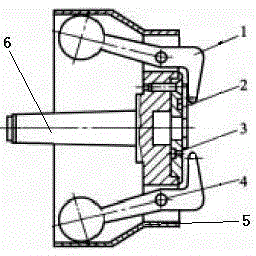
[0016] like figure 1 Shown is a schematic structural view of the centrifugal clamp of the present invention; a centrifugal clamp of the present invention includes a clamp body 5 provided with a cavity and no less than two claws 1 arranged on the clamp body 5, and the claws 1 are hinged On the clamp body 5 and one end of which extends into the cavity, and the other end extends to the end of the clamp body 5, a positioning disc 2 is provided at the end of the clamp body 5, and a positioning disc 2 is provided on the positioning disc 2 for workpiece positioning. stop pin 3.

[0017] In this embodiment, the workpiece is positioned by the end face of the positioning disc 2 and the stop pin 3, and the claw 1 pre-tightens the workpiece. After the machine is started, the claw 1 rotates with the spindle of the machine tool to generate centrifugal f...


PUM


Abstract

The invention discloses a centrifugal fixture. The centrifugal fixture comprises a fixture body provided with a cavity, and two or more clamping jaws arranged on the fixture body; the clamping jaws are hinged to the fixture body, one ends extend into the cavity, and the other ends extend to the end part of the fixture body; a positioning disc is arranged at the end part of the fixture body; and a stop pin for limiting a workpiece is arranged on the positioning disc. The centrifugal fixture rotates along with a main shaft of a machine tool to generate centrifugal force; the clamping jaws swing around shaft pins to automatically clamp the workpiece; and the centrifugal fixture is simple in structure, convenient for operation and reliable in clamping, saves both time and labors in workpiece unloading, is low in labor intensity of operators, and is high in production efficiency.

Description

technical field [0001] The invention belongs to the technical field involving the use of centrifugal force, and in particular relates to a centrifugal clamp. Background technique [0002] When the machine tool is processing the cover plate hole or some shaft parts, the surface quality and position accuracy of the two ends of the surface are not high, and it is inevitable to leave a claw on one end surface of the workpiece when the end surface is used to drive the top clamping. Indentation is generally allowed. Using a three-jaw chuck to hold parts takes time and effort to disassemble parts. The operator has high labor intensity, low production efficiency, poor calibration accuracy of end faces and inner holes, long time, and low clamping efficiency. Low. Contents of the invention [0003] In view of this, the purpose of the present invention is to provide a centrifugal clamp, which generates centrifugal force by the rotation of the main shaft of the random machine tool, a...

Claims


Application Information

Patent Timeline
Patent Type & Authority Applications(China)
IPC IPC(8): B23B31/14
Inventor 郭伟
Owner CHONGQING BAOJUE MACHINERY EQUIP
Why Eureka
Try Eureka