Precise self-centering chuck suitable for super-large workpieces

A self-centering chuck, super-large technology, applied in the direction of the chuck, can solve the problems of increased friction, excessive radial size, deviation, etc., to achieve high clamping and positioning precision, stable meshing rotation, The effect of ensuring positioning accuracy

Active Publication Date: 2016-07-20
ZHEJIANG 81 PRECISION MACHINERY CO LTD
View PDF12 Cites 36 Cited by
  • Summary
  • Abstract
  • Description
  • Claims
  • Application Information

AI Technical Summary

Problems solved by technology

Solve the problem that traditional chucks are difficult to stably clamp annular workpieces whose radial dimensions are too large or even exceed the outer diameter of the chuck
[0004] Although this application solves the problem that the stability of the annular workpiece with a large radial dimension is difficult to guarantee when clamping, there are still some deficiencies: the application uses four split-type plate fixtures to clamp the annular workpiece respectively. The four positions distributed by the cross, through the inner stopper and outer stopper on the plate-shaped fixture and the ball screws respectively provided on it, tighten the inner and outer circular surfaces of the ring-shaped workpiece, so as to realize the clamping of the ring-shaped workpiece In this process, the tightening of the ball screw requires manual operation, and the manual operation makes it impossible for the four plate-shaped fixtures to tighten the ring workpiece at the same time, and the tightening force received by the ring workpiece at these four places cannot be guaranteed to be consistent, resulting in the clamping of the ring workpiece. If the grip is not firm, it is easy to deviate and collide with the tool during the turning process; in addition, the ball screws set on the inner stopper and outer stopper are in point contact with the inner and outer circular surfaces of the ring-shaped workpiece respectively. The contact area between the two is small, and when there are small flaws or pits on the inner and outer circular surfaces of the annular workpiece, it is difficult to achieve precise clamping of the annular workpiece
[0005] Chinese invention patent 201410725732.7 discloses a three-jaw chuck, three slots are evenly distributed on the base, and first screw holes are arranged on the inner surface of the slots, and clamping devices are installed in the first screw holes; The above-mentioned clamping device includes a screw, on which there is a movable moving seat and claws connected to the moving seat, and one end of the screw extends out of the base and is connected with the motor. This invention solves the need for manual clamping of the traditional chuck, time consuming problem
Although this invention drives the claws to move back and forth through the motors to drive the corresponding screw rods to realize automatic clamping, there are still some problems: it is difficult to keep the output torques of the three motors consistent and synchronized during the working process, and when clamping extra-large workpieces, The friction between the screw and the nut pair is increased, and the loss is large, which leads to a change in the distance that the motor drives the screw to drive the corresponding jaws to move, so that the jaws cannot clamp the workpiece at the same time, and cannot realize self-centering and positioning clamps. Low holding accuracy, difficult to meet high-precision machining requirements
[0006] In summary, the field of modern mechanical numerical control machining is increasingly oriented towards mass customization and batch-scale production, and traditional fixtures can no longer meet the current production needs.

Method used


Image

  • Precise self-centering chuck suitable for super-large workpieces
  • Precise self-centering chuck suitable for super-large workpieces
  • Precise self-centering chuck suitable for super-large workpieces

Examples


Embodiment 1

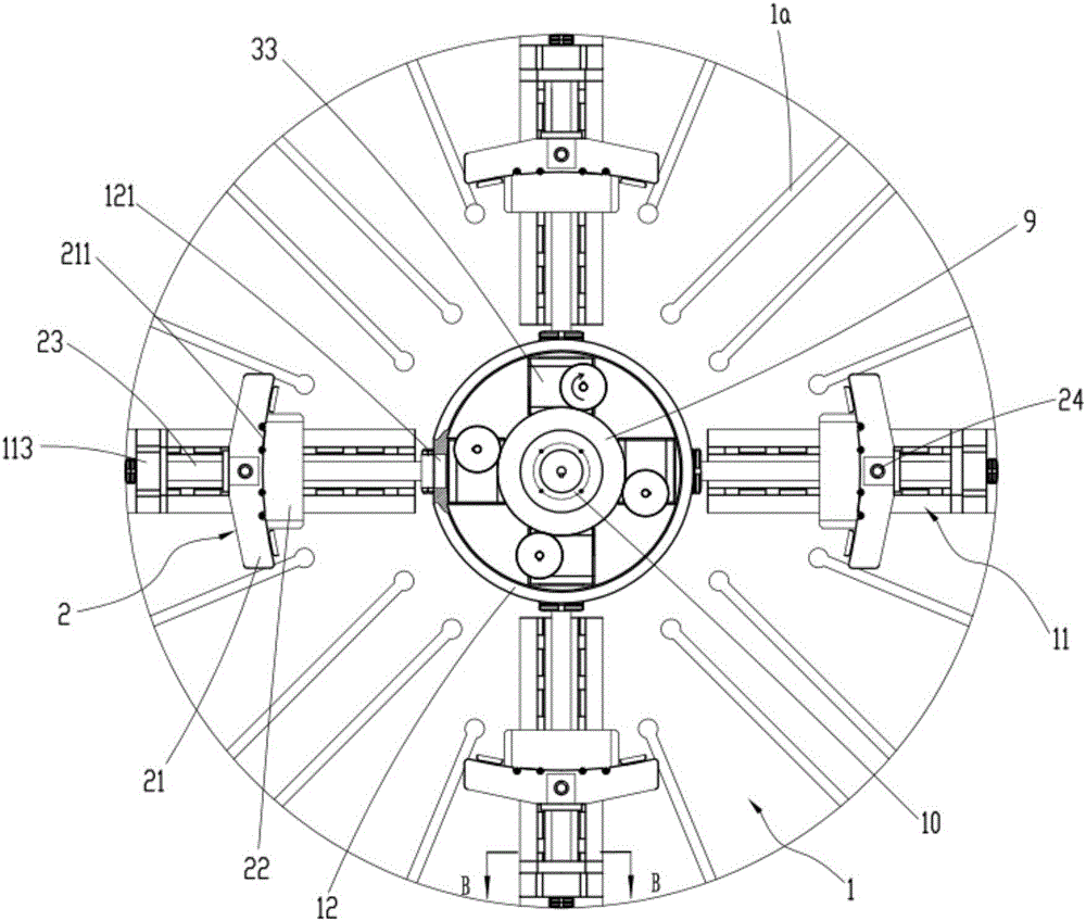
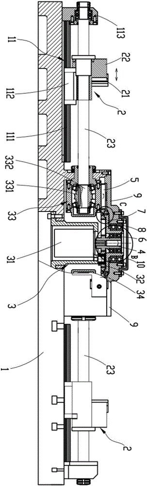
[0037] like figure 2 and image 3 As shown, the present invention provides a precision self-centering chuck suitable for extra-large workpieces, including a disc body 1 and a plurality of jaw mechanisms 2 slidably arranged on the disc body 1, and the disc body 1 is also provided with A jaw drive mechanism 3 that drives multiple jaw mechanisms 2 to clamp or loosen, the jaw drive mechanism 3 includes a numerically controlled torque motor 31, a plurality of transition gears 32, a secondary envelope reducer 33, and a first gear 34, Internal teeth 341 and external teeth 342 are respectively provided on the inner and outer circular surfaces of the first gear 34, and the numerically controlled torque motor 31 is arranged on the middle part of the disc body 1, and the motor shaft of the numerically controlled torque motor 31 is equipped with motor teeth 4, A plurality of transition gears 32 are evenly arranged between the motor teeth 4 and the first gear 34, and are all meshed with ...


PUM


Abstract

The invention relates to a precise self-centering chuck suitable for super-large workpieces. The precise self-centering chuck suitable for the super-large workpieces comprises a chuck body and a plurality of jack catch mechanisms arranged on the chuck body in a sliding mode. A jack catch driving mechanism is further arranged on the chuck body and comprises a numerical control moment motor, a plurality of transition gears, a plurality of double-enveloping speed reducers and a first gear. The inner circular surface and the outer circular surface of the first gear are provided with inner teeth and outer teeth correspondingly. The numerical control moment motor is provided with motor teeth. The multiple transition gears are all engaged with the motor teeth and the inner teeth of the first gear. The outer teeth of the first gear are engaged with second gears of the multiple double-enveloping speed reducers. The double-enveloping speed reducers drive the jack catch mechanisms to reciprocate to clamp or release the annular workpieces to be machined. The numerical control moment motor is used for sequentially driving the multiple transition gears and the double-enveloping speed reducers to rotate in a matched mode, so that the multiple jack catch mechanisms move inwards or outwards synchronously. The super-large annular workpieces are subjected to automatic centering clamping or releasing, and the clamping positioning accuracy is high.

Description

technical field [0001] The invention relates to the technical field of mechanical clamping, in particular to a precision self-centering chuck suitable for clamping extra-large ring parts. Background technique [0002] The workpiece clamping device is a device used to clamp the workpiece on the machine tool. It mainly uses the movable jaws evenly distributed on the chuck seat to move radially to clamp and position the workpiece. as attached figure 1 It is a schematic diagram of a three-jaw chuck in the prior art, including a chuck body 10a, jaws 20, a first bevel gear 30 and a second bevel gear 40, and a through hole 101 for placing a workpiece is provided in the middle of the chuck body 10a, The jaws 20 are three and are evenly arranged at an angle of 120° on the jaw track 50 on the end face of the chuck body 10a; the second bevel gear 40 meshes with the first bevel gear 30 and the second bevel gear 40 The back side is provided with a spiral groove 60; the end of the first...

Claims


Application Information

Patent Timeline
Patent Type & Authority Applications(China)
IPC IPC(8): B23B31/163
CPCB23B31/16004B23B31/16012
Inventor 陈仁波董志勇李远江刘荣格郑学军许磊王德东王力
Owner ZHEJIANG 81 PRECISION MACHINERY CO LTD
Why Eureka
Try Eureka