
Grinding machine with a grinding tool for roller grinding two workpieces

A technology for grinding tools and grinding machines, which is applied in the direction of grinding bed, grinding tools, grinding machines, etc. It can solve the problems of inaccuracy and vibration of workpieces, achieve good precision and realize the effect of precision

Inactive Publication Date: 2016-07-20
KLINGELNBERG AG
View PDF3 Cites 3 Cited by
  • Summary
  • Abstract
  • Description
  • Claims
  • Application Information

AI Technical Summary

Problems solved by technology

Occurring rolling deviations often lead to vibrations, which ultimately lead to imprecise workpieces

Method used


Image

  • Grinding machine with a grinding tool for roller grinding two workpieces
  • Grinding machine with a grinding tool for roller grinding two workpieces
  • Grinding machine with a grinding tool for roller grinding two workpieces

Examples


Embodiment Construction

[0035] Terms used in connection with this description are also used in related publications and patents. However, it is to be noted that these terms are used for better understanding only. The concept of the present invention and the protection scope of the patent claims should not be limited when interpreted due to the specific choice of terms. The invention is readily transferable to other terminology systems and / or technical fields. Terminology will be applied accordingly to other technical fields.

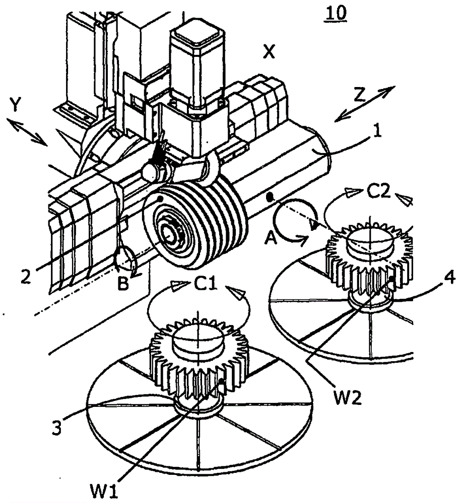
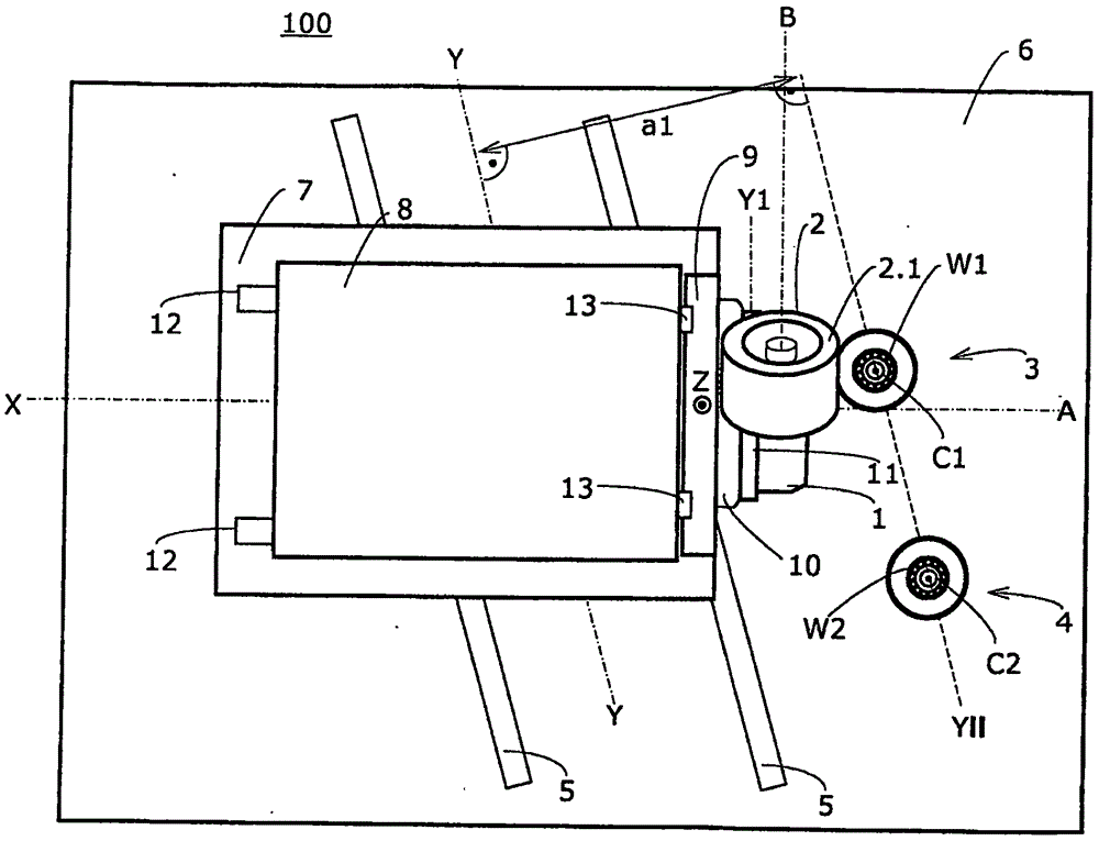
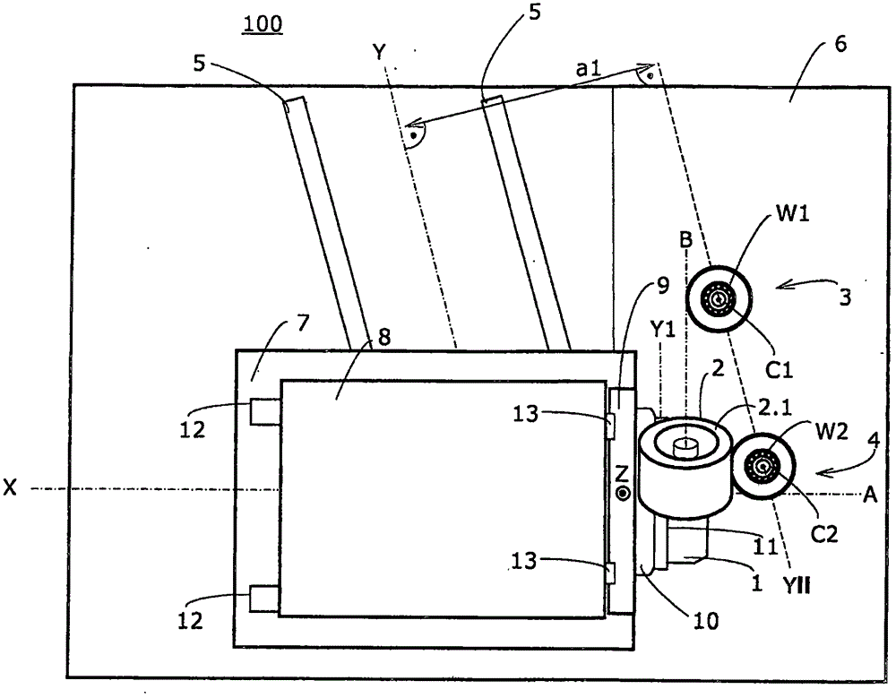
[0036] The grinding machine 100 according to the invention is equipped with a tool spindle 1 for receiving a grinding tool 2 and driving the grinding tool in rotation about a tool axis of rotation B (also called tool axis in short). In addition, the grinding machine 100 comprises a stationary first workpiece spindle 3 for receiving the first workpiece W1 and a stationary second workpiece spindle 4 for receiving the second workpiece W2. A first axis of rotation C1 associated wi...


PUM


Abstract

Grinding machine (100) includes a tool spindle (1, 1.1) for receiving and rotationally driving a grinding tool (2) about a tool axis (B) of rotation, a first workpiece spindle (3) for receiving a first workpiece (W1), and a second workpiece spindle (4) for receiving a second workpiece (W2), wherein the first workpiece spindle (3) and the second workpiece spindle (4) are arranged on one longitudinal side of the grinding tool (2) received on the tool spindle (1, 1.1); both workpiece spindles (3, 4) are arranged parallel to one another; the tool spindle (1) is configured to be able to move along a first linear guiding piece (5) parallel to a horizontal inclined axis (Y); the first workpiece spindle (3) and the second workpiece spindle (4) are separated from the horizontal inclined axis (Y) with the same vertical horizontal distance (a1); and the tool rotation axis (B) and the horizontal inclined axis (Y) form a closed angle (W) being greater than 0 DEG in the horizontal projection.

Description

technical field [0001] The subject of the invention is a device. In particular, it relates to a device for producing grinding comprising two workpiece spindles. Background technique [0002] There are various concepts for arranging the individual axes in machine tools designed for machining workpieces. In this case, on the one hand, try to achieve an optimal cost-use ratio. On the other hand, first and foremost in mass production, the value is often calculated in terms of productivity or the production capacity of this machine tool. [0003] Machine tools based on tool change are known which are able to provide a suitable tool for machining a workpiece in each case depending on the machining phase. Such a machine tool may have a tool carousel, for example, which is rotatable. Other machine tools operate with workpiece axes arranged so that they can pivot. For example, the machine tool according to EP2305409B1 comprises two workpiece spindles which are pivoted about resp...

Claims


Application Information

Patent Timeline
IPC IPC(8): B23F1/02
CPCB23F1/023B23F5/04B23F23/04B23Q1/60B23Q1/623B23Q39/028B24B27/0023B24B37/20B24B41/02
Inventor F·布克施I·格莱克斯纳C·布里登L·黑克斯
Owner KLINGELNBERG AG
Learn More