
Poking and separating type automatic cup falling device

An automatic and cup-dropping technology, which is applied in the directions of packaging, transportation and packaging, and unstacking of objects, etc., can solve the problems of poor accuracy, narrow application range, and poor separation effect, so as to achieve reasonable structure and accurate action Reliable, drop-accurate results

Active Publication Date: 2016-07-20
BENGBU SAIYA MACHINERY
View PDF6 Cites 5 Cited by
  • Summary
  • Abstract
  • Description
  • Claims
  • Application Information

AI Technical Summary

Problems solved by technology

The defect of the existing cup dropping device is that it is generally only suitable for the separation of cylindrical cups, and for some cups such as polygonal columns, the effect of pulling off is not good, and the scope of application is narrow; Entirely by free fall into the cavity on the formwork, the accuracy of the cup falling into the formwork is not good

Method used

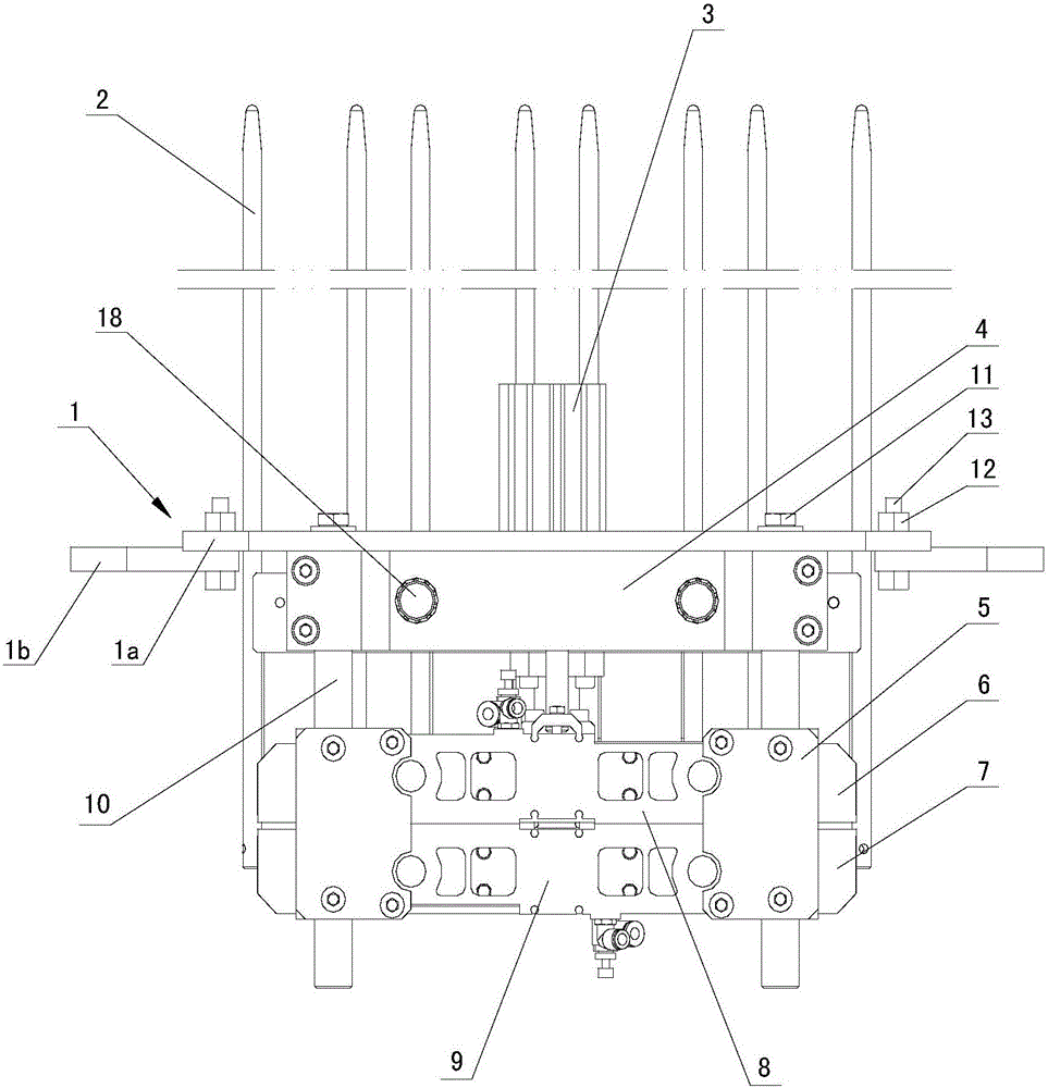
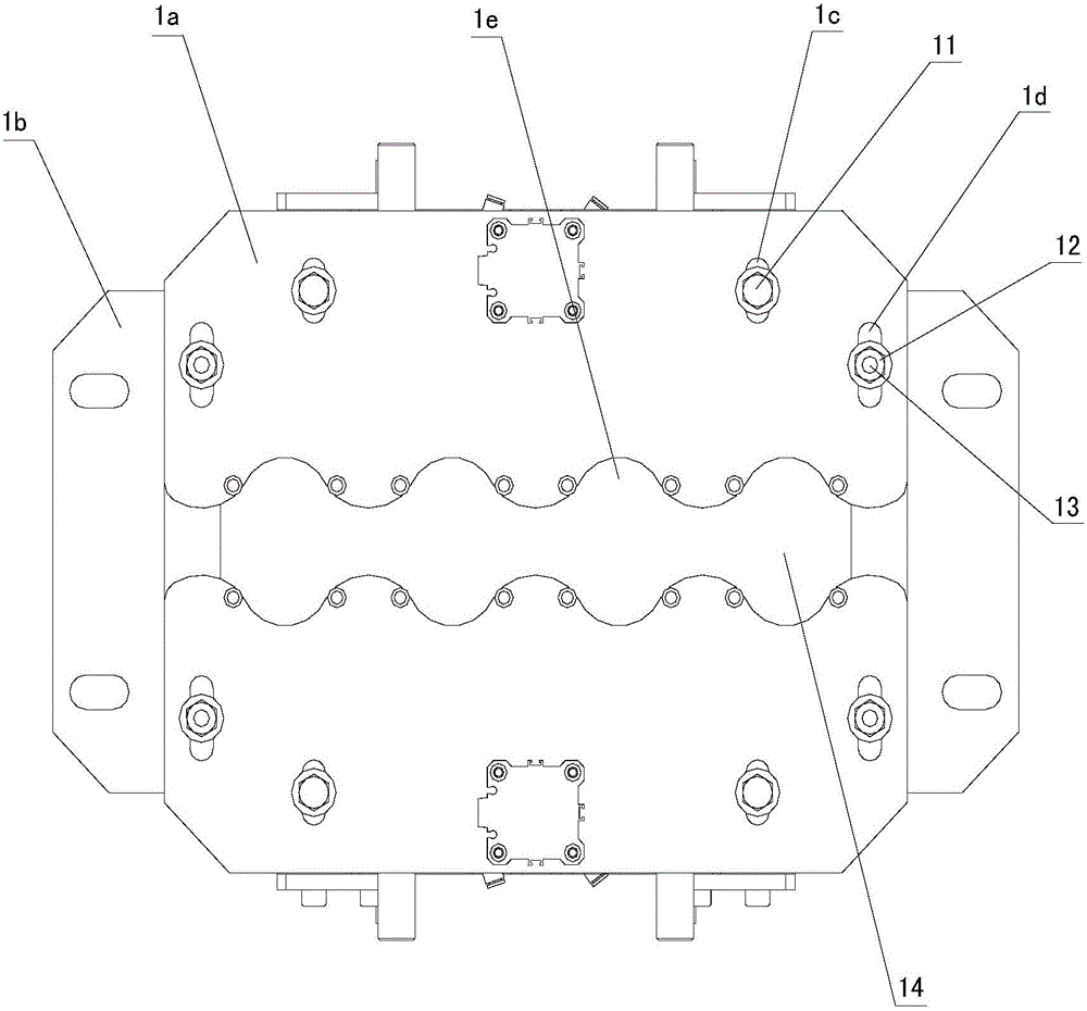
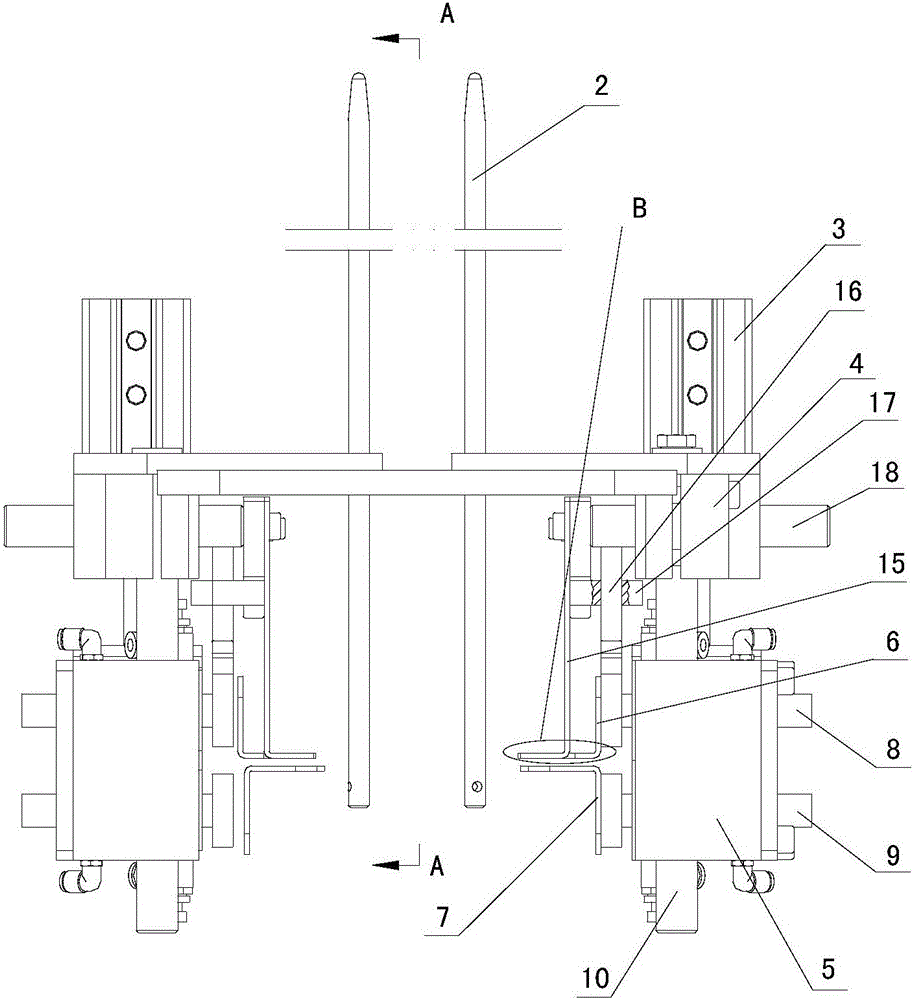

Image

  • Poking and separating type automatic cup falling device
  • Poking and separating type automatic cup falling device
  • Poking and separating type automatic cup falling device

Examples


Embodiment Construction

[0013] The present invention is further described below in conjunction with embodiment and accompanying drawing.

[0014] see figure 1 , figure 2 , image 3 , Figure 4

[0015] The pull-off type automatic cup drop device provided by the present invention has a platen 1, and a row of through holes 14 for passing through the packaging cups are arranged on the platen. A set of railings 2 are fixed on the edge of each through hole 14 to pass through the center of each through hole. The vertical plane of the line is the center plane, and two sets of pull-off mechanisms are arranged symmetrically along the center plane below the platen 1 . Each set of pull-off mechanism has three cylinders, wherein the first cylinder 3 is fixed on the upper side of the platen 1, the second cylinder 8 and the third cylinder 9 are located below the platen 1 and are jointly fixed with a cylinder frame 5, the second The piston rod of a cylinder 3 is vertical, and the piston rods of the second cyl...


PUM


Abstract

Disclosed is a poking and separating type automatic cup falling device. Rails are fixed to the edge of each through hole in a table board; a vertical face passing through the center line of each through hole is used as a center face; two sets of poking and separating mechanisms on the lower portion of the table board are symmetrically arranged along the center face; in each set of poking and separating mechanism, a first air cylinder is fixed to the upper side of the table board, and a second air cylinder and a third air cylinder are located on the lower portion of the table board and fixed together to an air cylinder rack; piston rods of the first air cylinders are connected with the corresponding air cylinder racks; pin columns are disposed on bases fixed to the lower side of the table board; the pin columns are connected with one group of upper poking forks; supports are connected to the upper poking forks; poking rods penetrating through the supports are connected with piston rods of the second air cylinders; the piston rods of the second air cylinders are connected with one group of middle poking forks; and piston rods of the third air cylinders are connected with one group of lower poking forks. The first air cylinders can control the air cylinder racks to move up and down; the second air cylinders can control the upper poking forks and the middle poking forks to be opened or closed; and the third air cylinders can control the lower poking forks to be opened or closed. All the air cylinders are controlled to act in sequence so that a pile of cups stacked up together in each group of rails can be poked and separated one by one.

Description

technical field [0001] The invention relates to a beverage processing device, in particular to an automatic cup dropping device in a cup-packed beverage processing equipment. Background technique [0002] In the beverage processing equipment with paper cups as the outer packaging, it is necessary to set up a cup drop device that puts the cups into the template. The basic structure of an existing cup drop device is as follows: a row of through holes for passing through the packaging cups is opened on a plate, a set of railings are fixed on the edge of each through hole, and a pull-off mechanism is provided under the platen. The mechanism has a reciprocating wedge-shaped fork plate. Its working principle is: put a stack of cups nested together in each group of railings, and the wedge-shaped fork plate is in the reciprocating motion to pull the bottom of the stack of cups away, and the cup at the bottom and the top After the cup is separated, it falls freely into the formwork...

Claims


Application Information

Patent Timeline
Patent Type & Authority Applications(China)
IPC IPC(8): B65B43/42B65G59/06B65G59/10
CPCB65B43/42B65G59/062B65G59/105
Inventor 王姚魏徽崔海伦杨永生司华洋
Owner BENGBU SAIYA MACHINERY
Learn More